
Methods and systems for optimizing frequency modulation atomic force microscopy

a frequency modulation and atomic force technology, applied in the field ofatomic force microscopy, can solve the problems of many questions and controversies, false interpretation of drive signal changes, and the general failure of the technology to meet expectations

Active Publication Date: 2017-06-06
MCGILL UNIV
View PDF6 Cites 0 Cited by
  • Summary
  • Abstract
  • Description
  • Claims
  • Application Information

AI Technical Summary

Benefits of technology

The invention aims to improve the accuracy of atomic force microscopy (AFM) by reducing errors introduced in energy dissipation measurements and tracking the frequency shift caused by the interaction between the cantilever and the sample. This is achieved by measuring the transfer function at a constant predetermined amplitude, controlling the effects of non-linearities and convolution effects, and feeding forward a correction signal derived in dependence upon at least the measured frequency shift during making measurements on the sample. The technical effect of the invention is to enhance the accuracy and precision of AFM measurements.

Problems solved by technology

However, to date the technique has generally not fulfilled expectations.
However, to date the unexplained variability in experimental data has prevented progress in AFM based energy dissipation studies and associated scientific insights and has led to many questions and controversies.
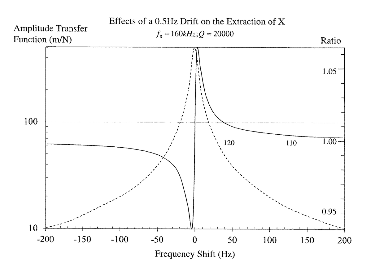
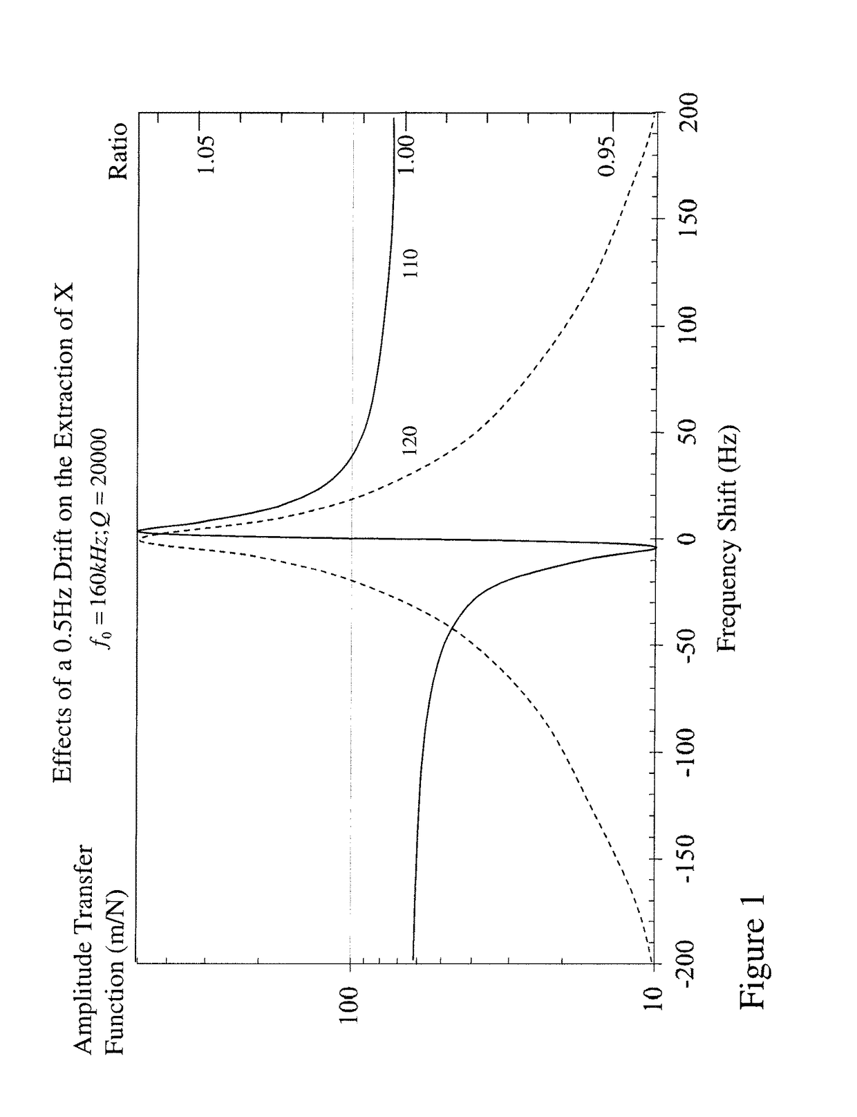
Omitting this measurement can lead to false interpretation of changes in the drive signal which relate to the physics of the FM-AFM system being considered to be those arising from the tip-sample physics.
However, this contrasts with dissipative forces, where experiment and theory within the prior art often disagree by several orders of magnitude.

Method used


Image

  • Methods and systems for optimizing frequency modulation atomic force microscopy
  • Methods and systems for optimizing frequency modulation atomic force microscopy
  • Methods and systems for optimizing frequency modulation atomic force microscopy

Examples


Embodiment Construction

[0041]The present invention is directed to atomic force microscopy (AFM) and in particular to frequency modulation atomic force microscopy.

[0042]The ensuing description provides exemplary embodiment(s) only, and is not intended to limit the scope, applicability or configuration of the disclosure. Rather, the ensuing description of the exemplary embodiment(s) will provide those skilled in the art with an enabling description for implementing an exemplary embodiment. It being understood that various changes may be made in the function and arrangement of elements without departing from the spirit and scope as set forth in the appended claims.

[0043]This invention pertains to a method and device which performs an automated and accurate measurement of the transfer function of the piezoacoustic excitation system of a frequency modulation atomic force microscope (FM-AFM). This measurement of is then used to calibrate the FM-AFM signals (drive amplitude and frequency shift) into a dissipat...


PUM


Abstract

Energy dissipation measurements in Frequency Modulation-Atomic Force Microscopy (FM-AFM) should provide additional information for dynamic force measurements as well as energy dissipation maps for robust material properties imaging as they should not be dependent directly upon the cantilever surface interaction regime. However, unexplained variabilities in experimental data have prevented progress in utilizing such energy dissipation studies. The inventors have demonstrated that the frequency response of the piezoacoustic cantilever excitation system, traditionally assumed flat, can actually lead to surprisingly large apparent damping by the coupling of the frequency shift to the drive-amplitude signal. Accordingly, means for correcting this source of apparent damping are presented allowing dissipation measurements to be reliably obtained and quantitatively compared to theoretical models. The methods are non-destructive and can be both easily and routinely integrated into FM-AFM measurements within vacuum environments where measurements exploiting prior art solutions cannot be performed.

Description

CROSS REFERENCE TO RELATED APPLICATIONS[0001]This patent application claims the benefit of U.S. Provisional Patent Application U.S. 61 / 609,994 filed Mar. 13, 2012 entitled “Methods and Systems for Optimizing Frequency Modulation Atomic Force Microscopy”, the entire contents of which are included by reference.FIELD OF THE INVENTION[0002]The present invention relates to atomic force microscopy (AFM) and in particular to frequency modulation atomic force microscopy.BACKGROUND OF THE INVENTION[0003]Atomic force microscopy (AFM) or scanning force microscopy (SFM) is a very high-resolution type of scanning probe microscopy, with demonstrated resolution on the order of fractions of a nanometer, more than 1000 times better than the optical diffraction limit. Accordingly over the past 30 years the AFM has become one of the foremost tools for imaging, measuring, and manipulating matter at the nanoscale level. The information is gathered by “feeling” the surface with a mechanical probe wherein...

Claims


Application Information

Patent Timeline
Patent Type & Authority Patents(United States)
IPC IPC(8): G01Q60/24G01Q30/06G01Q60/34
CPCG01Q60/24G01Q30/06G01Q60/34
Inventor LABUDA, ALEKSANDERGRUTTER, PETERMIYAHARA, YOICHIPAUL, WILLIAMROY-GOBEIL, ANTOINE
Owner MCGILL UNIV
Learn More