Power equipment and harmonic suppression method in power equipment

a technology of power equipment and harmonic suppression, which is applied in the direction of harmonic reduction arrangement, dc motor speed/torque control, ac network to reduce harmonics/ripples, etc., can solve the problems of low electric motor operation efficiency and increase in temperature, and achieve the effect of improving electric motor operation efficiency and saving power

Active Publication Date: 2017-06-06
SHIGA FUNCTIONAL WATER LAB CORP
View PDF8 Cites 0 Cited by
  • Summary
  • Abstract
  • Description
  • Claims
  • Application Information

AI Technical Summary

Benefits of technology

[0008]According to the above configuration, a harmonic voltage for generating a rotational magnetic flux counteracting a rotational magnetic flux acting as a braking force, when the electric motor is operated, is added to the configuration, so that the harmonic is suppressed, the operation efficiency of the electric motor is improved, and a power saving effect can be obtained.

Problems solved by technology

The harmonic voltages lower an operational efficiency of the electric motor, and lead to an increase in temperature.

Method used


Image

  • Power equipment and harmonic suppression method in power equipment
  • Power equipment and harmonic suppression method in power equipment
  • Power equipment and harmonic suppression method in power equipment

Examples


Embodiment Construction

[0044]Hereinafter, embodiments of the invention will be described in detail with reference to the drawings.

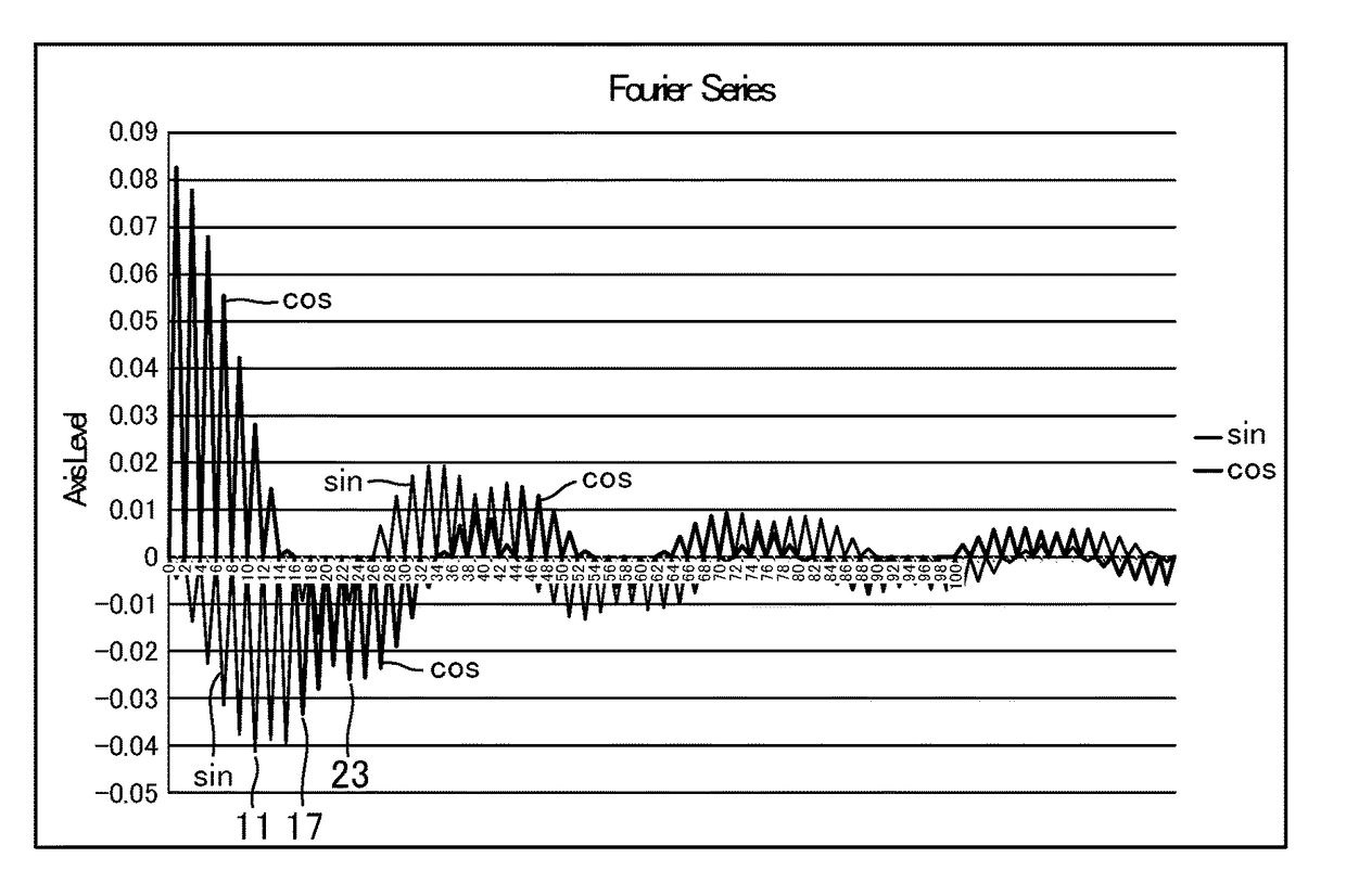
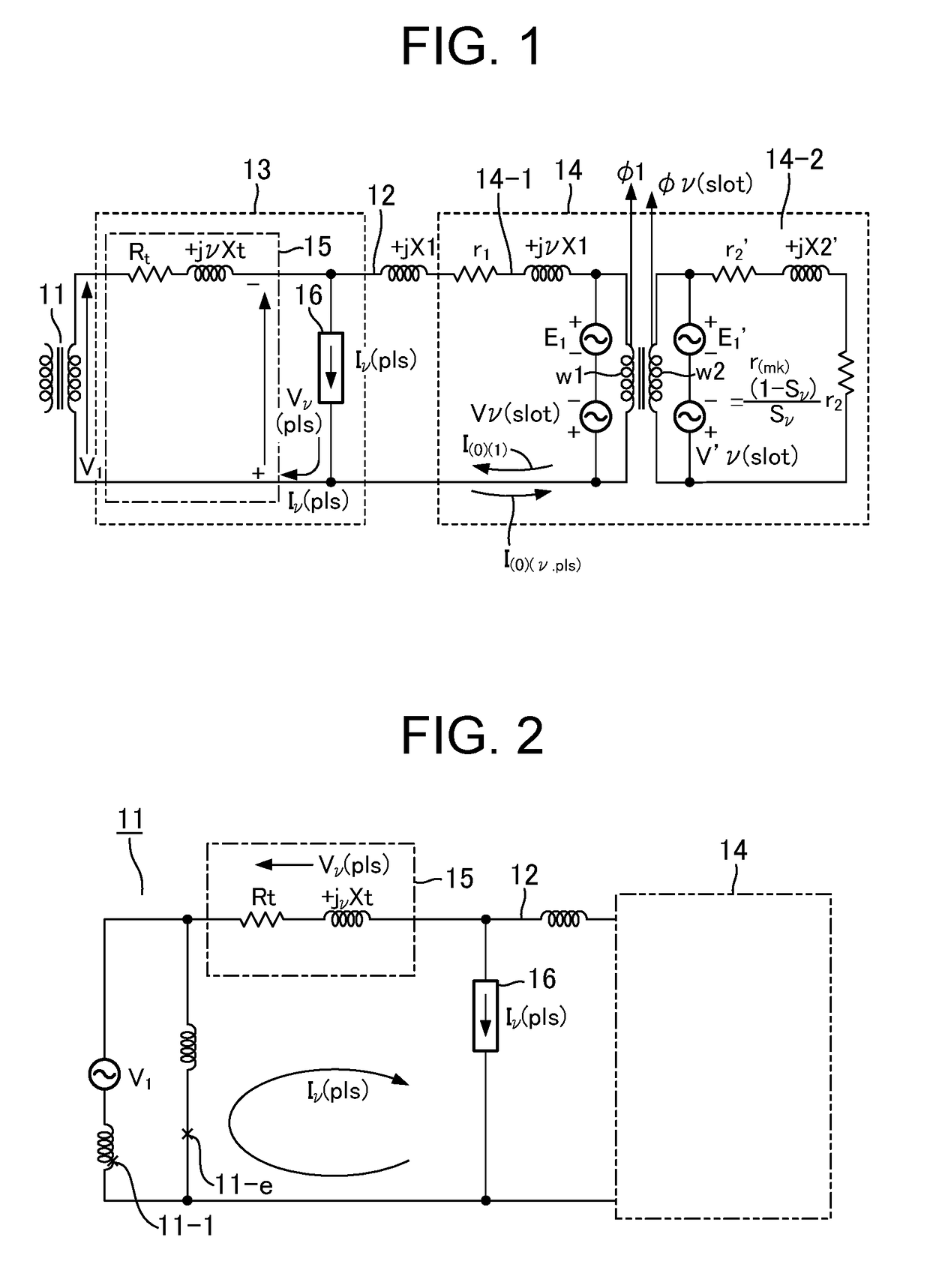
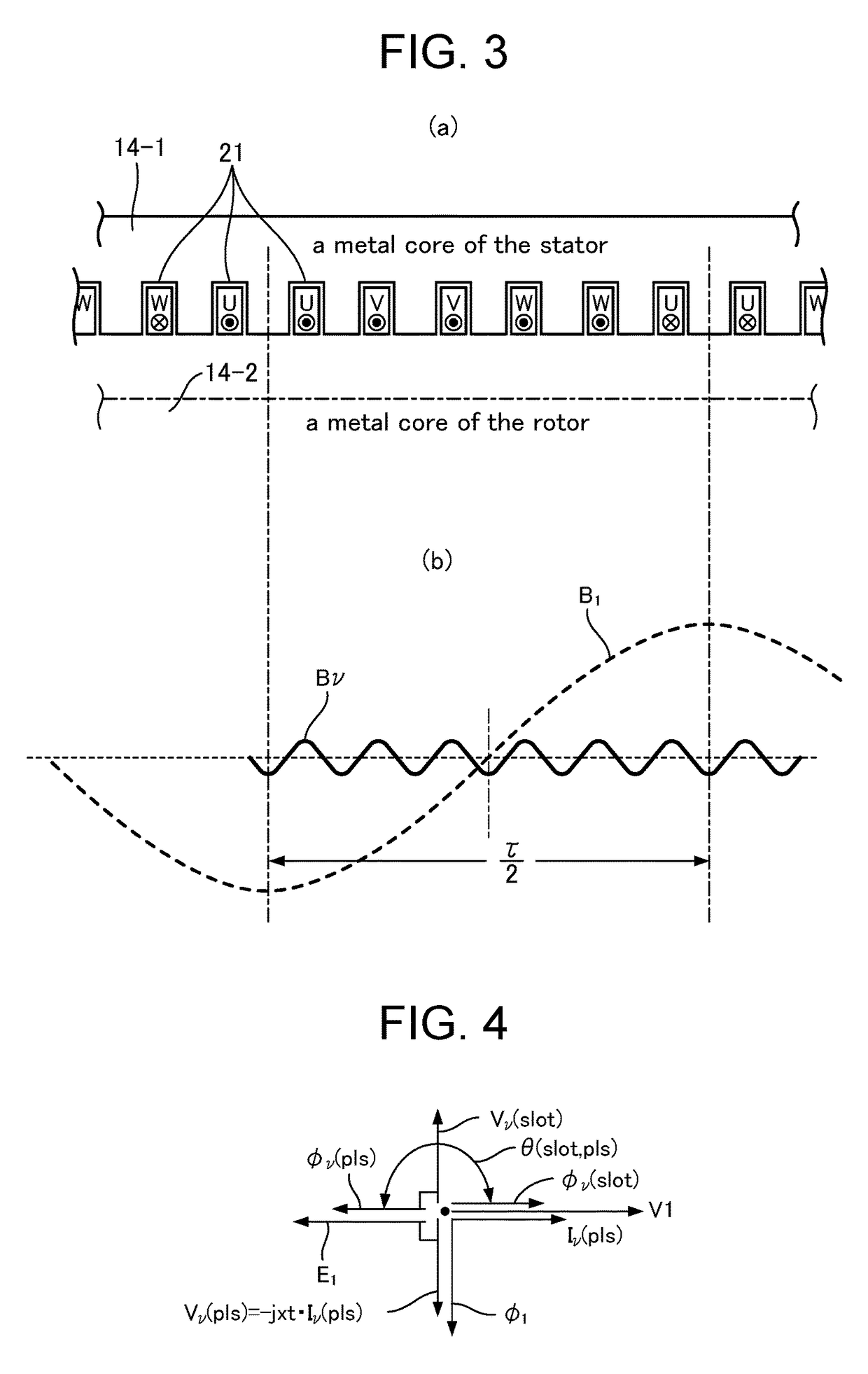
[0045]FIG. 1 illustrates an equivalent circuit representing a relation between a power source transformer 11, a power trunk line 12, a harmonic generation unit 13, and an induction motor 14, all of which are included in a power equipment. The harmonic generation unit 13 includes a reactance circuit 15 and a harmonic current generator 16. As illustrated in the drawing, the harmonic current generator 16 may be provided in the vicinity of the power source transformer 11, or may be provided in the vicinity of an input terminal of the induction motor 14 connected to a terminal of the power trunk line (also referred to as a low-voltage trunk line) 12.

[0046]The power trunk line (100V, 200V, 400V, and so on) 12 is derived from both ends of the secondary winding of the power source transformer 11. A power source voltage V1 is generated between both ends of the secondary winding of the p...


PUM


Abstract

Provided is a power equipment which obtains a power saving effect according to the operation of an electric motor by providing a harmonic suppression function on the side of a power trunk line for supplying power to the electric motor without changing the electric motor side. The power equipment includes an electric motor (14) which is supplied with power from a power trunk line (12) connected to a power source transformer (11) to be operated. A harmonic generation unit (13) is provided in the power trunk line (12) and generates a harmonic voltage having a phase opposed to but the same degree as that of a harmonic voltage of a degree acting as a braking force on a rotor (14-2) in a rotational magnetic flux of harmonics generated between a stator (14-1) and the rotor when the electric motor (14) is operated.

Description

[0001]This application is the U.S. national phase of International Application No. PCT / JP2014 / 005945 filed 27 Nov. 2014, which designated the U.S. and claims priority to JP Patent Application No. 2013-271651 filed 27 Dec. 2013, the entire contents of each of which are hereby incorporated by reference.TECHNICAL FIELD[0002]Embodiments of the present invention relate to a power equipment and a harmonic suppression method in the power equipment which includes an electric motor supplied with power from a power trunk line connected to a power source transformer.BACKGROUND ART[0003]In general, an induction motor is widely used as a power source of various types of equipment. In such type of electric motor, a power source voltage is supplied from a power trunk line to a primary winding provided in a stator to generate a rotation magnetic field. The rotation magnetic field causes a rotation torque in a rotor to rotate. In this case, harmonic voltages are generated due to the structure of the...

Claims


Application Information

Patent Timeline
Patent Type & Authority Patents(United States)
IPC IPC(8): H02J3/01H02P29/50H02P7/00H02P29/00
CPCH02P29/50H02J3/01Y02E40/40
Inventor SHIGA, SEIKI
Owner SHIGA FUNCTIONAL WATER LAB CORP
Why Eureka
Try Eureka