Fuel depot in space

a fuel depot and space technology, applied in the field of aerospace industry, can solve the problems of limited space size and bulky design of current designs, and achieve the effect of reducing the volume of the overall craft, and facilitating the need for in-flight refueling operations

Active Publication Date: 2017-06-13
GATEWAY GALACTIC INC
View PDF11 Cites 16 Cited by
  • Summary
  • Abstract
  • Description
  • Claims
  • Application Information

AI Technical Summary

Problems solved by technology

There are currently no other platforms in orbit that can perform a refueling operation on this level, as current designs are too bulky and limited in size due to mass considerations.
This saves money and space associated with launching this craft.

Method used


Image

  • Fuel depot in space
  • Fuel depot in space
  • Fuel depot in space

Examples


Embodiment Construction

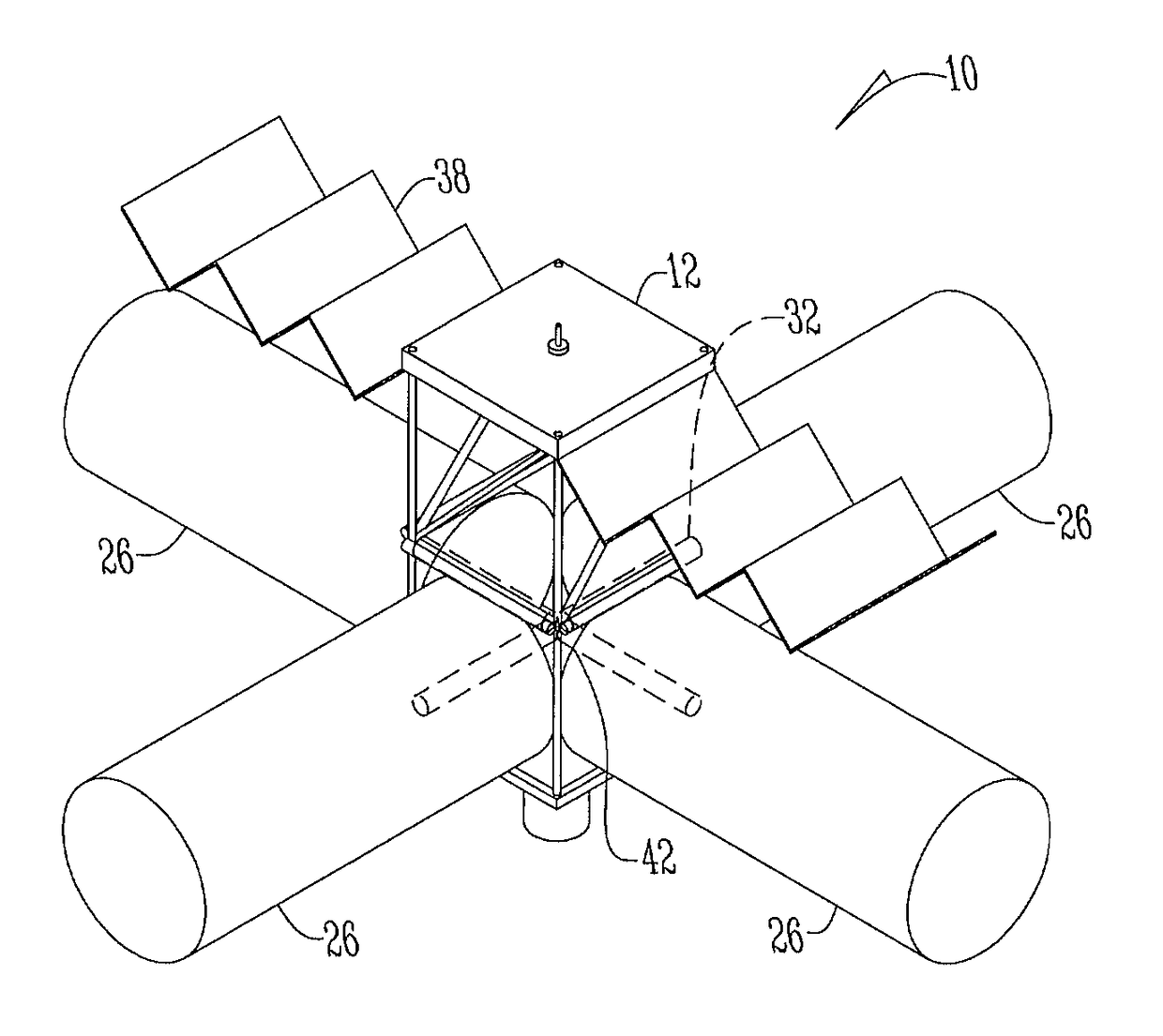
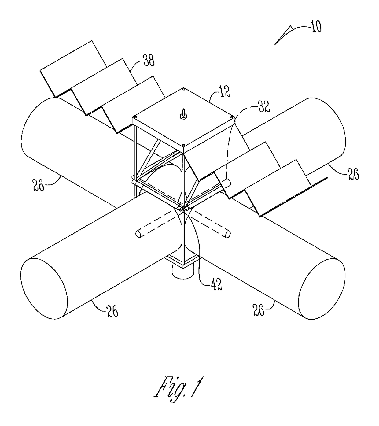
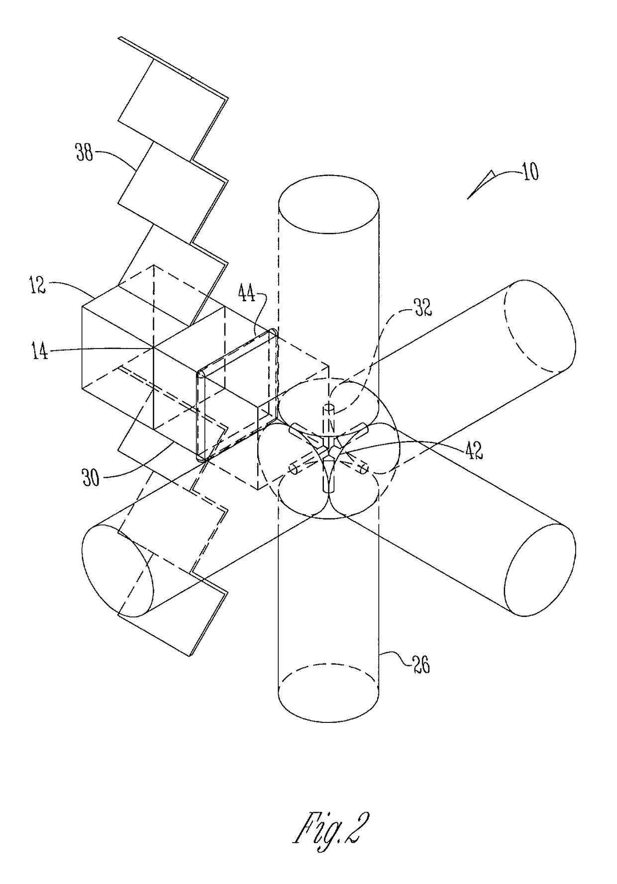
[0010]Referring to the figures, a fuel depot 10 is disclosed and is comprised of a housing 12 that contains a GNC system 14 and all the parts integrated specifically to handle the computing tasks of keeping the fuel depot 10 in orbit and performing fueling operations autonomously. Within the housing 12 is a power management system 16 to collect power from a solar panel assembly 18 and store the power for later use. Surrounding the housing 12 are mounts 20 for a reaction control system (RCS) 22 to keep the orientation and orbit of the fuel depot 10 stable during fueling operations and idle operations.

[0011]A pump housing 24 holds the necessary equipment to pump the components from the tanks 26 and out to a craft 28 during fueling. Each fuel tank 26 has a designated pump 30 to avoid the complications of contaminating a fuel component with oxidizer or vice versa, thus keeping the mixtures pure to be mixed later by the receiving craft 28. The pumps 30 are connected to individual pipe sy...


PUM


Abstract

A fuel depot in space is provided. The fuel depot has a collapsible housing with a guidance, navigation, and control (GNC) system, a power management system, and a reaction control system (RNC). Connected to the housing are a plurality of fuel tanks that are connected via collapsible rods. The fuel tanks have pipe systems that are in communication with a plurality of pumps to transfer fuel from the tanks through a refueling arm and into a spacecraft during refueling.

Description

CROSS REFERENCE TO RELATED APPLICATION[0001]This application claims the benefit of U.S. Provisional Application No. 62 / 106,021 filed Jan. 21, 2015.BACKGROUND OF THE INVENTION[0002]This invention relates to the aerospace industry. More specifically, the invention advances the current capabilities of in space refueling procedures for long missions and expands the distance that spacecrafts can travel by allowing spacecrafts to refuel during their stages in orbit.[0003]There are currently no other platforms in orbit that can perform a refueling operation on this level, as current designs are too bulky and limited in size due to mass considerations. The invention is a fuel depot placed in orbit to allow for refueling. The fuel depot is able to collapse down to a manageable size for a single launch into orbit and then to fully expand autonomously to its full size once in orbit. This saves money and space associated with launching this craft. The station is also fully autonomous, making th...

Claims


Application Information

Patent Timeline
Patent Type & Authority Patents(United States)
IPC IPC(8): B64G1/10B64G1/64B64G1/22B64G1/40B64G1/44B64G1/24B64G1/26
CPCB64G1/1078B64G1/222B64G1/402B64G1/646B64G1/242B64G1/26B64G1/44B64G2001/224B64G1/2227
Inventor MYERS, JUSTIN J.RICHARDSON, FLOYD R.
Owner GATEWAY GALACTIC INC
Why Eureka
Try Eureka