Hinge having movable shaft

a technology of movable shafts and hinges, which is applied in the direction of casings/cabinets/drawers, instruments, casings/cabinets/drawers, etc., can solve the problems of shaft movement, damage or deformation of display, and achieve the effect of preventing deformation or damage of display

Active Publication Date: 2017-06-13
LIANHONG TECH
View PDF13 Cites 73 Cited by
  • Summary
  • Abstract
  • Description
  • Claims
  • Application Information

AI Technical Summary

Benefits of technology

[0006]An object of the invention is to provide a hinge having movable shafts. The movable shafts are mounted to a display and a main body of an electronic device moving relative to each other to prevent deformation or damage of display when the display and the main body of the electronic device rotate relative to each other. The invention provides a hinge. The hinge in accordance with an exemplary embodiment of the invention includes a first shaft mounted to an upper plate and comprising a first gear and a first rod extending from the first gear; a second shaft mounted to a lower plate and comprising a second gear and a second rod extending from the second gear; a first guiding member, through which the first rod and the second rod extending, comprising a first up-inclined groove having a predetermined length and a first down-inclined groove having a predetermined length; a second guiding member disposed on the first rod and the second rod and comprising a second up-inclined groove having a predetermined length and a second down-inclined groove having a predetermined length; a guiding base disposed between the first shaft and the second shaft, mounted to the first guiding member and the second guiding member and comprising a first row of teeth engaging the first gear and a second row of teeth engaging the second gear, wherein the first rod extends through the first up-inclined groove and the second up-inclined groove to connect the upper plate, and the second rod extends through the first down-inclined groove and the second down-inclined groove to connect the lower plate.

Problems solved by technology

However, when the electronic devices are opened or closed, the shafts may move.
The movement of the shafts may cause damages or deformation of the display.

Method used


Image

  • Hinge having movable shaft
  • Hinge having movable shaft
  • Hinge having movable shaft

Examples


Embodiment Construction

[0024]The following description is of the best-contemplated mode of carrying out the invention. This description is made for the purpose of illustrating the general principles of the invention and should not be taken in a limiting sense. The scope of the invention is best determined by reference to the appended claims.

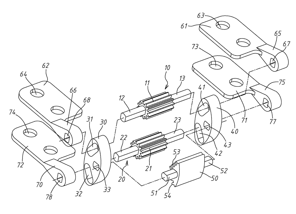
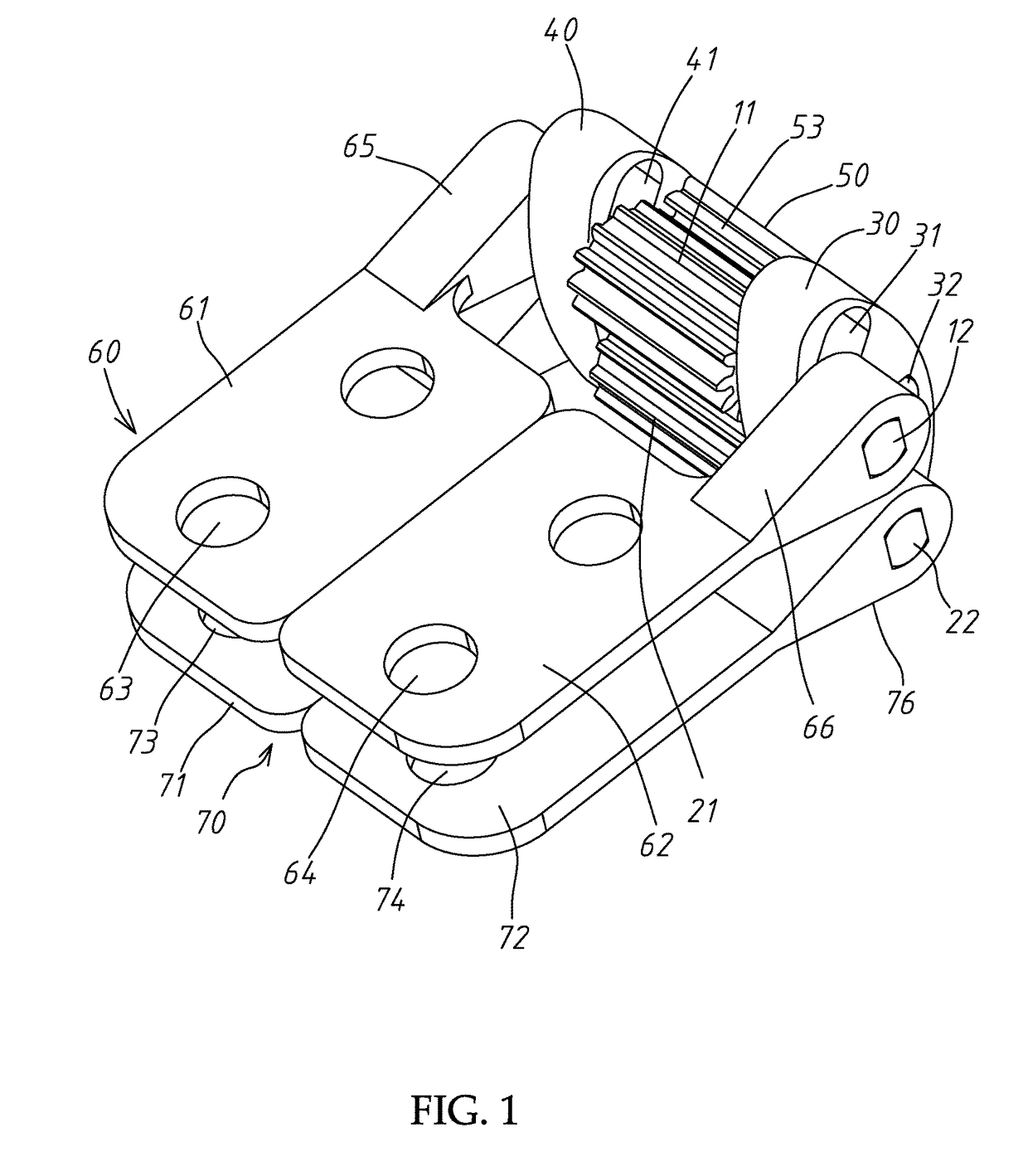
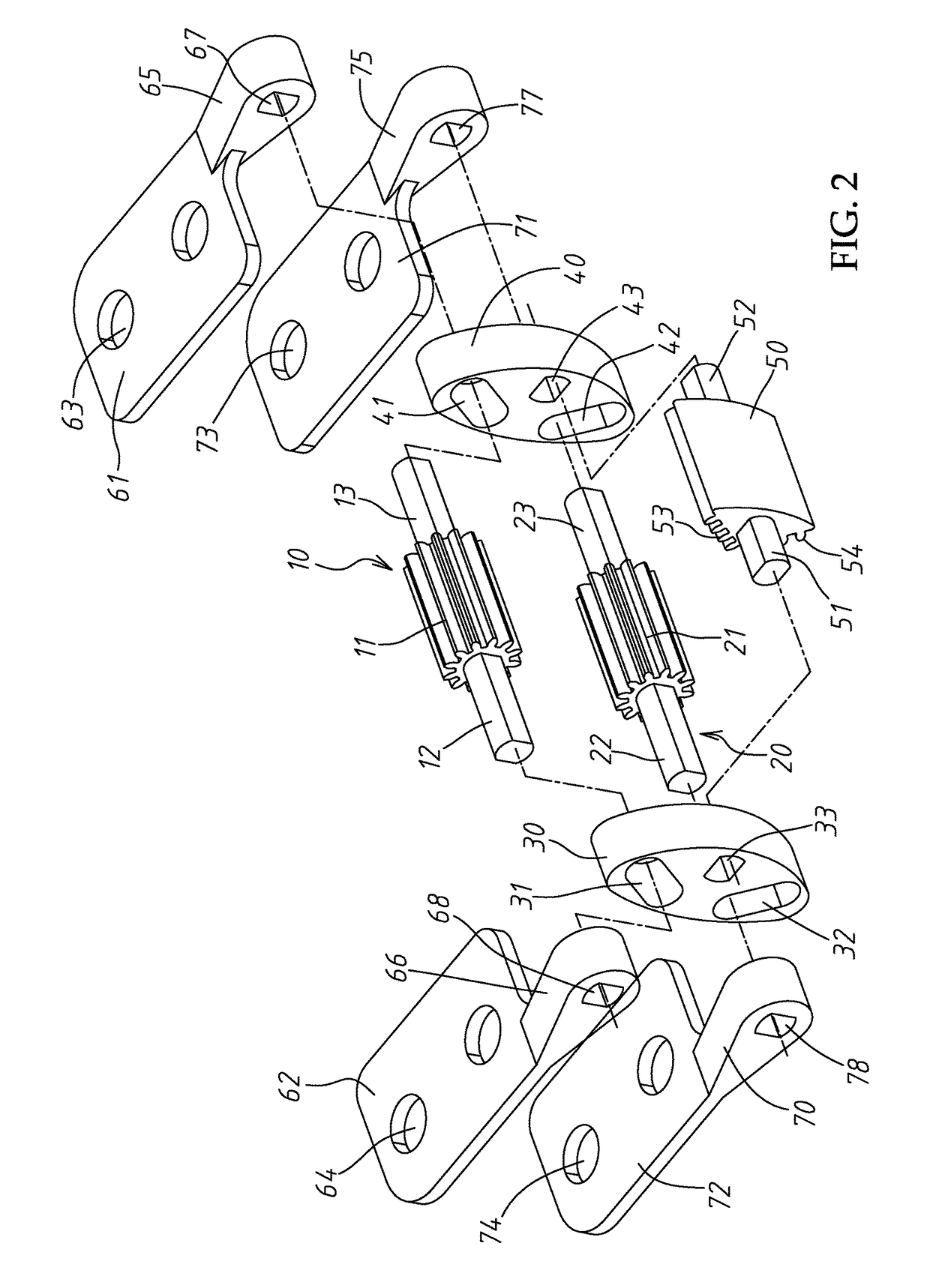
[0025]Referring to FIGS. 1 and 2, an embodiment of a hinge of the invention includes a first shaft 10 and a second shaft 20. The first shaft 10 and the second shaft 20 extend through a first guiding member 30 and a second guiding member 40. A guiding base 50 is disposed between the first shaft 10 and the second shaft 20. The first shaft 10 is connected to a upper plate 60, and the second shaft 20 is connected to a lower plate 70. The upper plate 60 and the lower plate 70 are fixed to two parts of an electronic device which are moved to become opened or closed, such as a display and a main body of an electronic device (not shown).

[0026]A first gear 11 is formed on a cen...


PUM


Abstract

A hinge includes at least one shaft set including a first shaft and a second shaft. The first shaft and the second shaft extend through a first guiding member and a second guiding member. A guiding base is disposed between the first shaft and the second shaft. The first shaft and the second shaft connect to an upper plate and a lower plate. The upper plate and the lower plate are connected to two rotatable parts of an electronic device. The first shaft and the second shaft moves relatively along with the rotation of the two rotatable parts of the electronic device.

Description

BACKGROUND OF THE INVENTION[0001]Field of the Invention[0002]The invention relates to a hinge having movable shaft and equipped to an electronic device and having a plurality movable shafts moving with rotation of the electronic device to prevent a display of the electronic device from damaging or breaking during the rotation.[0003]Description of the Related Art[0004]As IT industry rapidly develops, electronic information processing device develops from desktops to portable electron equipment, such as portable laptops and even tablets, smartphone or wearable devices. Display devices of these electronic devices also develops from rigid display to flexible display. The flexible display includes a glass substrate coated with a flexible plastic layer and has bendable, fordable and extensile characteristics. The flexible display is applied to hand phones, tablets and wearable devices.[0005]Conventional hinges for these electronic devices have different shafts mounted to display and main ...

Claims


Application Information

Patent Timeline
Patent Type & Authority Patents(United States)
IPC IPC(8): E05D3/18E05D3/12E05D3/06G06F1/16H05K5/02
CPCE05D3/18E05D3/122E05D3/06G06F1/1681H05K5/0226E05Y2900/606Y10T16/541
Inventor CHEN, CHIA-HUILIN, TZU-YUCHANG, CHIAO-FANG
Owner LIANHONG TECH
Why Eureka
Try Eureka