Pocket hole drilling machine

a drilling machine and pocket technology, applied in the field of pocket holes, can solve the problems of inconvenient and time-consuming process, inability to readily accommodate various material thicknesses, and add to the inconvenience and expense of these systems, and achieve the effects of improving safety by eliminating pinch points, convenient use of workpieces, and low cos

Active Publication Date: 2017-06-20
KREG ENTERPRISES
View PDF83 Cites 17 Cited by
  • Summary
  • Abstract
  • Description
  • Claims
  • Application Information

AI Technical Summary

Benefits of technology

[0019]A pocket hole drilling machine is presented. The pocket hole drilling machine has a cabinet made of a molded unitary monolithic piece. A monolithic top plate is connected to the cabinet with an opening in the middle for an insert plate which is positioned therein. A handle extends above the top plated as does a clamping assembly however actuating mechanics of the device move within the cabinet, thereby improving safety by eliminating pinchpoints. An adjustable fence assembly having cam locks connected thereto is also connected to the top plate. This arrangement provides a low cost, safe and efficient pocket hole drilling machine.

Problems solved by technology

Such a process is inconvenient and time-consuming.
Additionally, such clamps do not readily accommodate various material thicknesses.
Other devices utilize a one-step process, but require an expensive pneumatic air cylinder with a clamp pad to facilitate clamping.
The use of pneumatics further requires a source of air, i.e., an air compressor, which adds to the inconvenience and expense of these systems.
In addition, while there are previous pocket hole drilling machines, these machines are expensive and have unnecessarily complicated and un-ergonomic designs.
These machines also have moving parts exterior to the cabinet and they also lack desirable features.

Method used


Image

  • Pocket hole drilling machine
  • Pocket hole drilling machine
  • Pocket hole drilling machine

Examples


Embodiment Construction

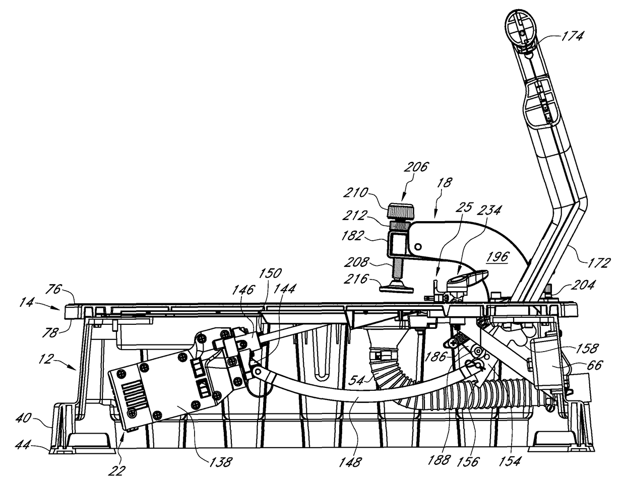
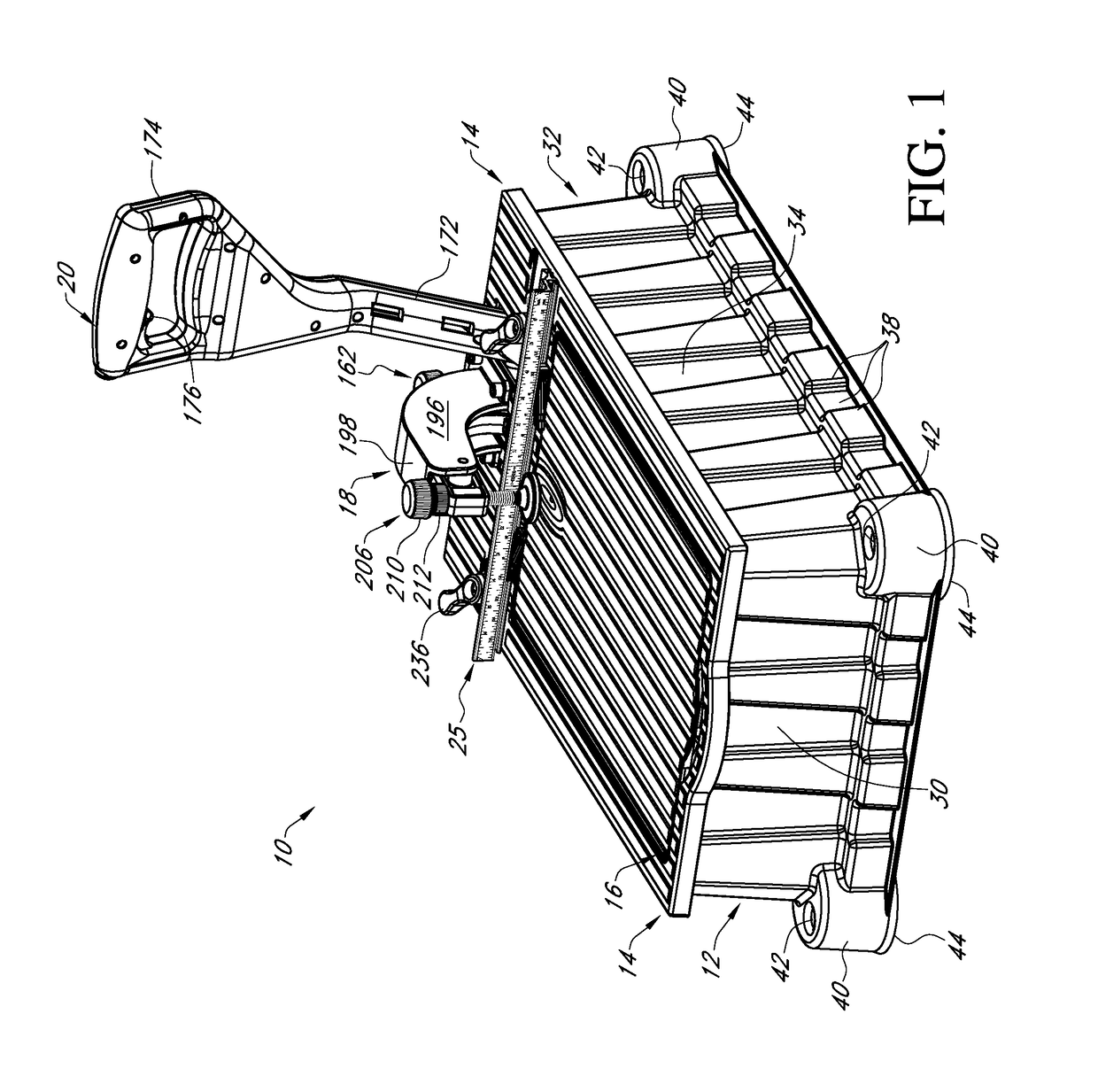
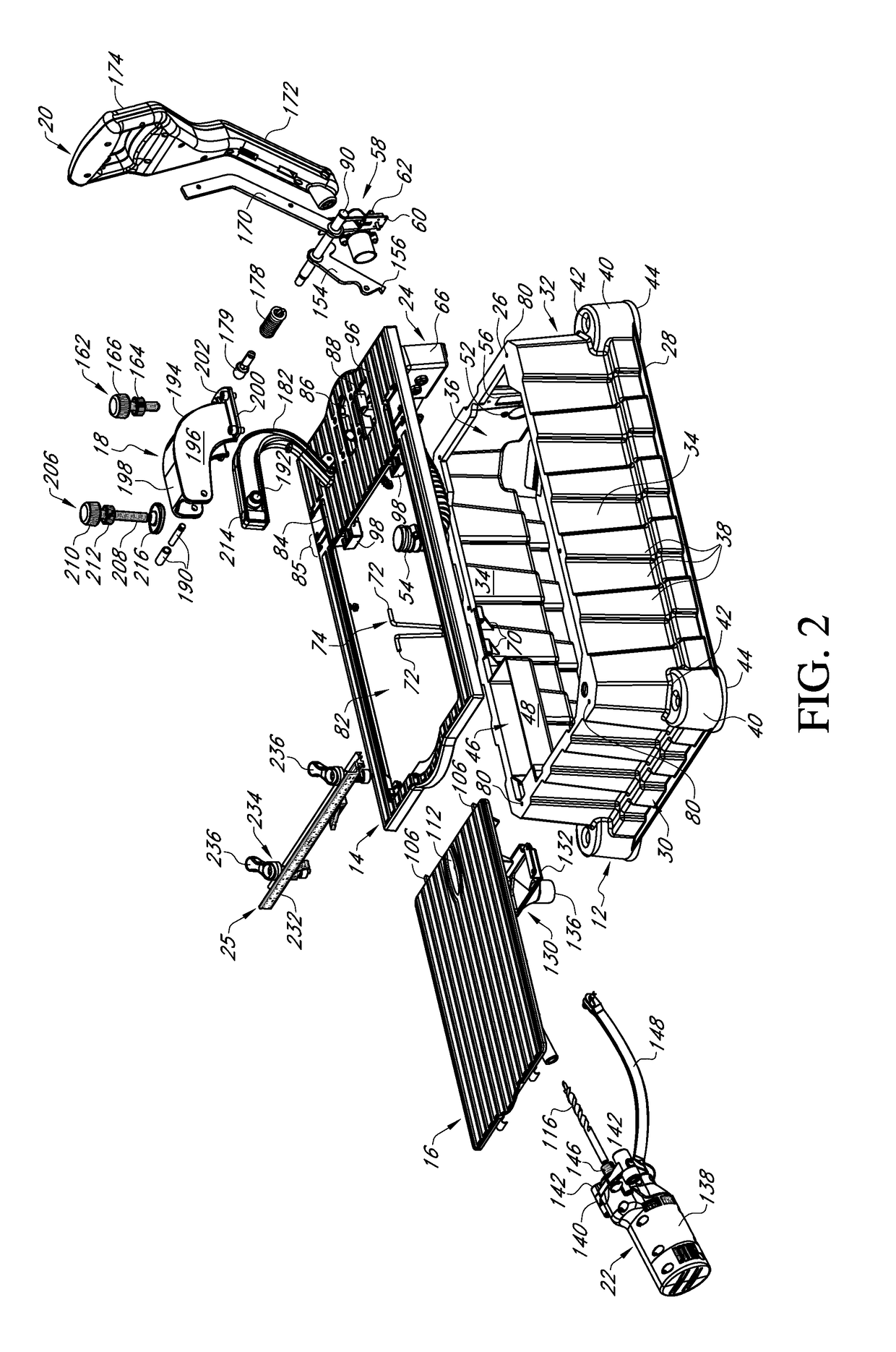
[0047]In the following detailed description, reference is made to the accompanying drawings which form a part hereof, and in which is shown by way of illustration specific embodiments in which the invention may be practiced. These embodiments are described in sufficient detail to enable those skilled in the art to practice the invention, and it is to be understood that other embodiments may be utilized and that mechanical, procedural, and other changes may be made without departing from the spirit and scope of the invention(s). The following detailed description is, therefore, not to be taken in a limiting sense, and the scope of the present invention is defined only by the appended claims, along with the full scope of equivalents to which such claims are entitled.

[0048]As used herein, the terminology such as vertical, horizontal, top, bottom, front, back, ends, sides, etc., are referenced according to the views presented. It should be understood, however, that the terms are used on...


PUM

PropertyMeasurementUnit
angleaaaaaaaaaa
angleaaaaaaaaaa
areaaaaaaaaaaa

Abstract

A pocket hole drilling machine is presented. The pocket hole drilling machine has a cabinet made of a molded unitary monolithic piece. A monolithic top plate is connected to the cabinet with an opening in the middle for an insert plate which is positioned therein. A handle extends above the top plated as does a clamping assembly however actuating mechanics of the device move within the cabinet, thereby improving safety by eliminating pinchpoints. An adjustable fence assembly having cam locks connected thereto is also connected to the top plate. This arrangement provides a low cost, safe and efficient pocket hole drilling machine.

Description

CROSS REFERENCE TO RELATED APPLICATION[0001]This application claims the benefit of U.S. Provisional Application No. 61 / 833,487 filed Jun. 11, 2013.FIELD OF THE INVENTION[0002]This invention relates to pocket holes. More specifically, and without limitation, this invention relates to a pocket hole drilling machine.BACKGROUND OF INVENTION[0003]There are many types of machines in use today for drilling holes such as dowel holes, pocket holes, and so forth, in various types of workpieces. Pocket hole wood joinery involves joining boards by inserting a fastener at an angle through the edge of one board into the other. Such joints are commonly used for face frames, cabinet boxes, leg-to-rail joinery in chairs and tables, and so forth. Drill guides, jigs, and pocket hole boring machines are used to drill the holes through which the fasteners or pocket screws are inserted into the adjoining workpiece.[0004]Conventional devices utilize a two-step process to manually clamp and then drill. Suc...

Claims


Application Information

Patent Timeline
Patent Type & Authority Patents(United States)
IPC IPC(8): B23B41/00B25B5/06B25B11/00B25B5/08B27C3/08B27C3/02B27B27/00B23Q3/18B23B47/28B23B47/00B23B39/00
CPCB23B47/00B23B47/288B23Q3/18B25B5/06B25B5/08B25B11/00B27B27/00B27C3/02B27C3/08B23B39/003B23B41/00B23B2247/10B23B2247/12Y10T408/03Y10T408/563
Inventor CLARK, SCOTT L.
Owner KREG ENTERPRISES
Why Eureka
Try Eureka