
Curtain wall mullion anchoring system

a curtain wall and mullion technology, applied in the direction of walls, constructions, building components, etc., can solve the problems of potential sealant line failure or wall panel connection failure, delay in job completion, and more time-consuming quality control inspection, and achieve the effect of convenient installation

Inactive Publication Date: 2017-06-20
ADVANCED BUILDING SYST
View PDF75 Cites 21 Cited by
  • Summary
  • Abstract
  • Description
  • Claims
  • Application Information

AI Technical Summary

Benefits of technology

The present invention is about mullion anchoring systems that allow for adjustments in all three directions to absorb large construction tolerances and reduce or eliminate the uplifting force caused by dead load and wind load. The systems use small concrete anchors to anchor curtain wall mullions to a concrete floor slab or spandrel beam / column. The systems also eliminate the overturning moment created by transmitting the dead load force over a point outside the floor slab edge, which eliminates uplifting force on the anchoring device. The system is easy to install, can adjust construction tolerances, and can anchor curtain wall mullions to a concrete floor slab without using anchor bolts or curtain wall mullions to a spandrel beam or column.

Problems solved by technology

Some functional disadvantages of slab edge embed anchoring systems include: (1) They require punching or notching through the slab edge concrete stop before pouring concrete for the protruding threaded steel rods for the connection bolts or for the exposure of the anchor channel; (2) It is extremely difficult to remedy incorrectly located embeds after the concrete slab cures; (3) In case of incorrectly located holes in the mullion, the mullion must be re-fabricated in the shop, causing potential job delays; (4) Quality control inspection is more time consuming since the anchoring components are outside the slab edge.
Some structural problems of a slab edge embed anchoring system include: (1) The anchor bolts are subjected to both shear and tensile stresses due to dead and cyclic wind loads, causing potential stress fatigue; (2) Use of slotted holes for construction tolerance adjustments means the structural connection strength against wind load reaction becomes a function of the distance from the connection bolt to the center of the slotted hole; therefore, either the worst condition or a higher safety factor must be considered; (3) Using slotted holes for left / right adjustment results in uneven wind load reactions on the double L-shaped mullion connection clips causing twisting of the mullion, producing potential sealant line failure or wall panel connection failure.
Some functional disadvantages of an on-slab embed anchoring system include: (1) It requires heavy hoisting equipment for the erection; (2) It is difficult to maintain the design position of the embed due to the fact that the embeds are often inadvertently kicked out of position or buried inside the slab during concreting operations, and it is costly to remedy the problem of incorrectly located embeds.
Some structural problems of prior art on-slab embed anchoring systems include: (1) The dead load reaction is transmitted from the mullion connection clip to a point on the bracket that overhangs the floor slab edge, and the overhanging distance depends on the amount of in / out construction tolerance adjustment.
It is cost prohibitive to solve this problem by relocating the mullion connection clip in the field since it will significantly slow down field productivity.
In prior art on-slab mullion anchoring systems, the uplifting force on the anchoring device generated by dead load is a long term load.

Method used


Image

  • Curtain wall mullion anchoring system
  • Curtain wall mullion anchoring system
  • Curtain wall mullion anchoring system

Examples


Embodiment Construction

[0047]Reference will now be made in detail to the preferred embodiments of the present invention, examples of which are illustrated in the accompanying drawings.

[0048]In order to better explain the working principles of the invention, the following will list terminology that will be used herein along with illustrative examples of the terminology. The list of terminology and illustrative examples are not intended to depart from or limit the plain and ordinary meaning of the terminology:

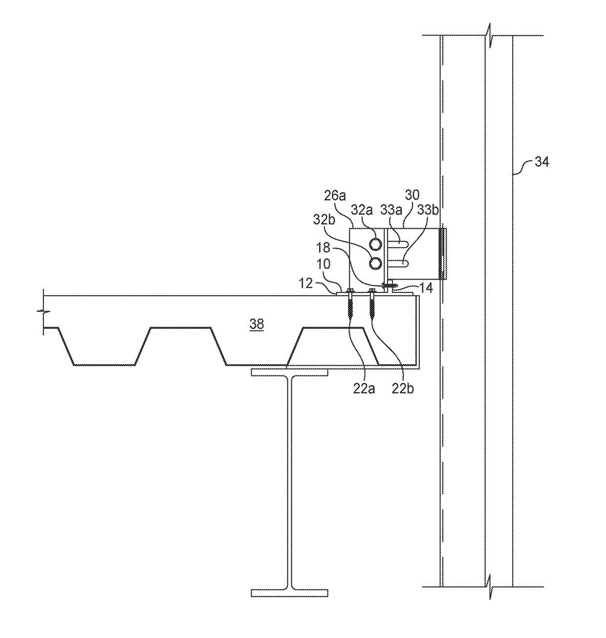
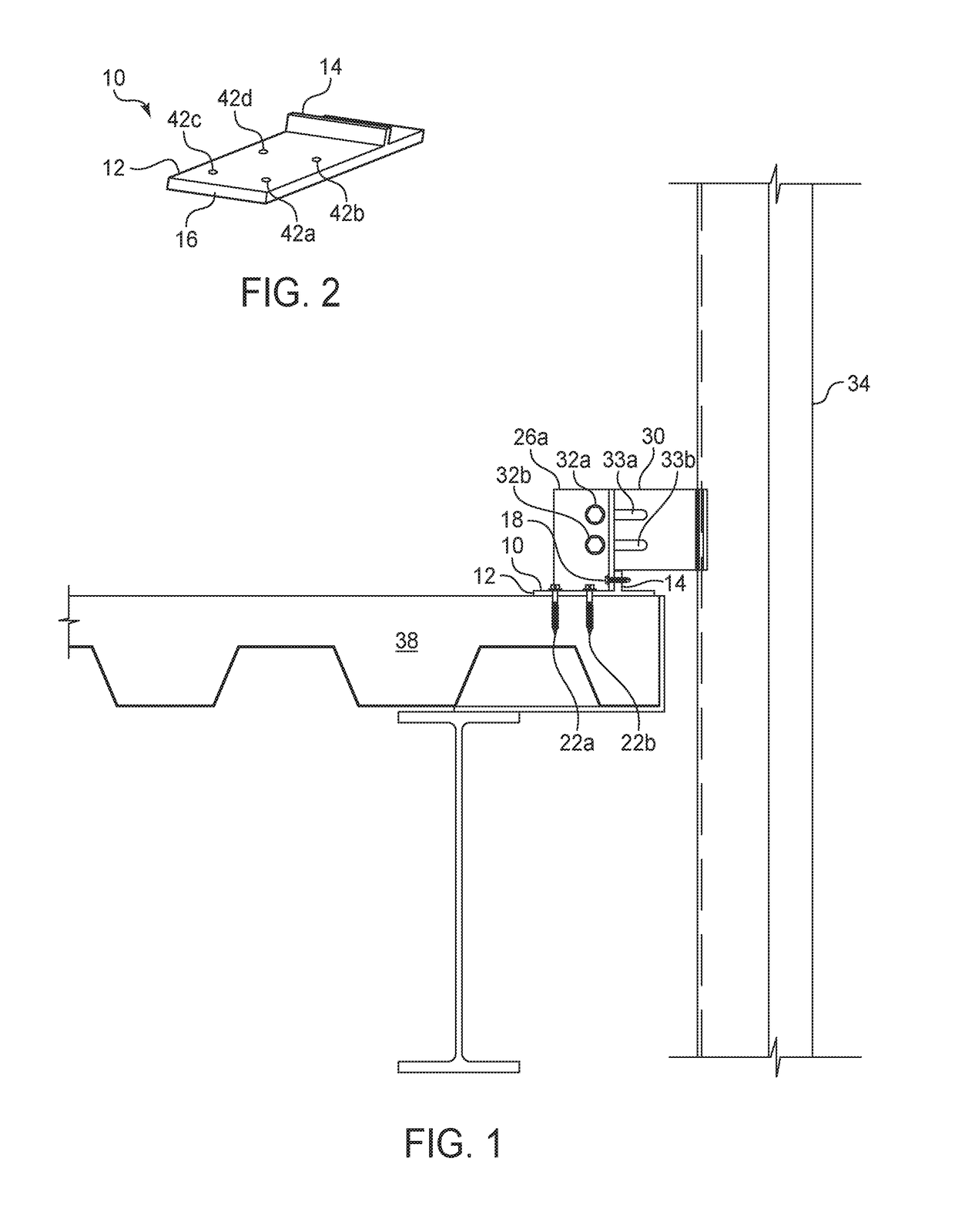
[0049]Mullion: one of a plurality of spaced apart structural members generally in the vertical direction used to structurally support weather sealing exterior wall panels. A mullion may be vertical or sloped, depending on the architectural design.

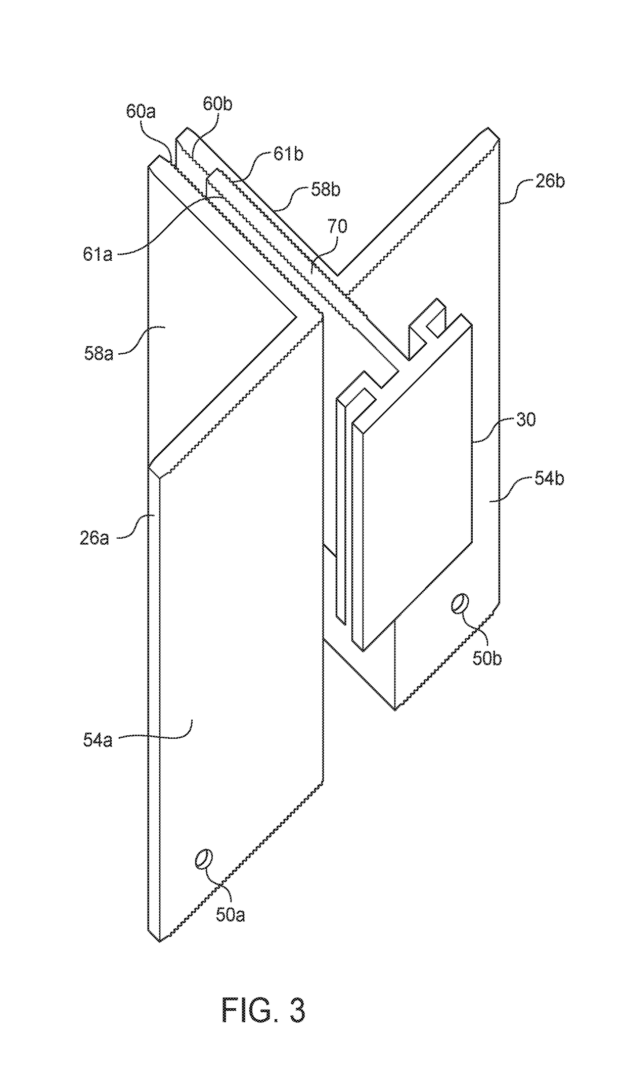
[0050]Anchoring Device: a structural device designed for anchoring a mullion at the wind and dead load reaction point onto a building structural element, such as a concrete floor slab or a building frame element such as a spandrel beam or a column. An anchorin...


PUM


Abstract

Curtain wall mullion anchoring systems for resisting dead load and negative wind load, and that permit three-way construction tolerance adjustments. The mullion anchoring systems include an anchoring device secured to a building structural element and attached to a mullion connection bridge, which is connected to a mullion connection clip, which is connected to a mullion. Uplifting forces on the anchoring device may be significantly reduced or even eliminated by transmitting dead load under negative wind load conditions from the mullion to the anchoring device at a point over the inside of a concrete floor slab, such that the dead load counteracts any uplifting force generated by the negative wind load.

Description

CROSS-REFERENCE TO RELATED APPLICATIONS[0001]This application claims the benefit under 35 U.S.C. §119(e) of the earlier filing dates of U.S. Provisional Patent Application No. 62 / 298,828 filed on Feb. 23, 2016, and U.S. Provisional Patent Application No. 62 / 303,797 filed on Mar. 4, 2016.BACKGROUND OF THE INVENTION[0002]1. Field of the Invention[0003]This invention relates to exterior curtain wall mullion anchoring system design.[0004]2. Description of the Background[0005]An exterior curtain wall system consists of three major components, namely, wall panels providing weather protection, mullions providing structural support to the wall panels, and mullion anchoring systems providing a structural connection between the mullions and a building structural element. Mullion anchoring systems carry the dead load weight of the wall panels and transfer the load to the building structure, typically at the building base or at intermediate floor slabs. Mullion anchoring systems also absorb pos...

Claims


Application Information

Patent Timeline
IPC IPC(8): E04B2/88E04B2/96E04B1/41
CPCE04B2/965E04B2/967E04B2/88E04B1/41E04B2/96E04B1/4107
Inventor TING, RAYMOND M. L.
Owner ADVANCED BUILDING SYST
Learn More