Shock absorber

a technology of shock absorber and shock absorber, which is applied in the direction of shock absorbers, springs/dampers functional characteristics, cycle equipment, etc., can solve the problems of the foregoing configuration of the shock absorber is not suitable for use, and the difficulty of setting a damping force separately for each one of the moving directions of the piston, etc., to achieve significant impairment of the favorable ride quality of the vehicle

Active Publication Date: 2017-06-20
KYB CORP
View PDF8 Cites 1 Cited by
  • Summary
  • Abstract
  • Description
  • Claims
  • Application Information

AI Technical Summary

Benefits of technology

[0005]Furthermore, when the shock absorber having the foregoing configuration is applied to a two-wheel vehicle, there is a possibility that the ride quality of the vehicle is significantly impaired if malfunction occurs in a control device that controls the amount of electric current supplied to the solenoid at around the maximum output, where the piston moves to a large extent in one direction as a result of the shock absorber being subjected to a large impact.
[0006]It is an object of the present invention to enable a shock absorber to adjust a damping force separately for each one of the moving directions of a piston, and also to maintain a favorable ride quality of a vehicle by reliably producing a damping force at around the maximum output.

Problems solved by technology

However, with the shock absorber having the foregoing configuration, it is difficult to set a damping force separately for each one of the moving directions of the piston.
For this reason, the shock absorber having the foregoing configuration is not suitable for use when a damping force needs to be set separately for each one of the moving directions of the piston, e.g., for a rear cushion that suspends a rear wheel of a two-wheel vehicle.
Furthermore, when the shock absorber having the foregoing configuration is applied to a two-wheel vehicle, there is a possibility that the ride quality of the vehicle is significantly impaired if malfunction occurs in a control device that controls the amount of electric current supplied to the solenoid at around the maximum output, where the piston moves to a large extent in one direction as a result of the shock absorber being subjected to a large impact.

Method used


Image

  • Shock absorber
  • Shock absorber
  • Shock absorber

Examples


Embodiment Construction

[0014]The following describes a shock absorber according to an embodiment of the present invention with reference to the drawings. Elements that are given the same reference sign throughout some drawings are the same as or equivalent to one another.

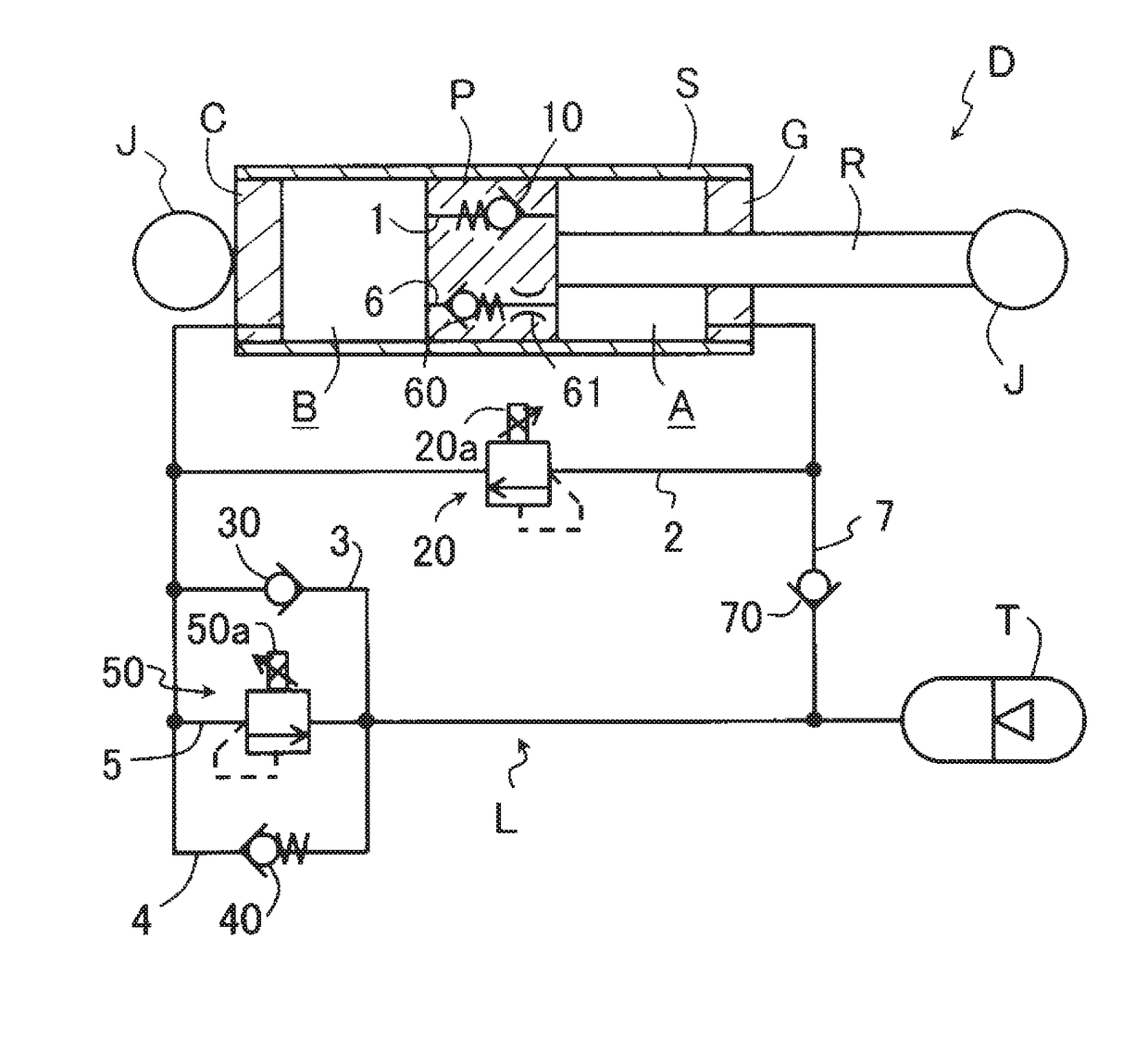
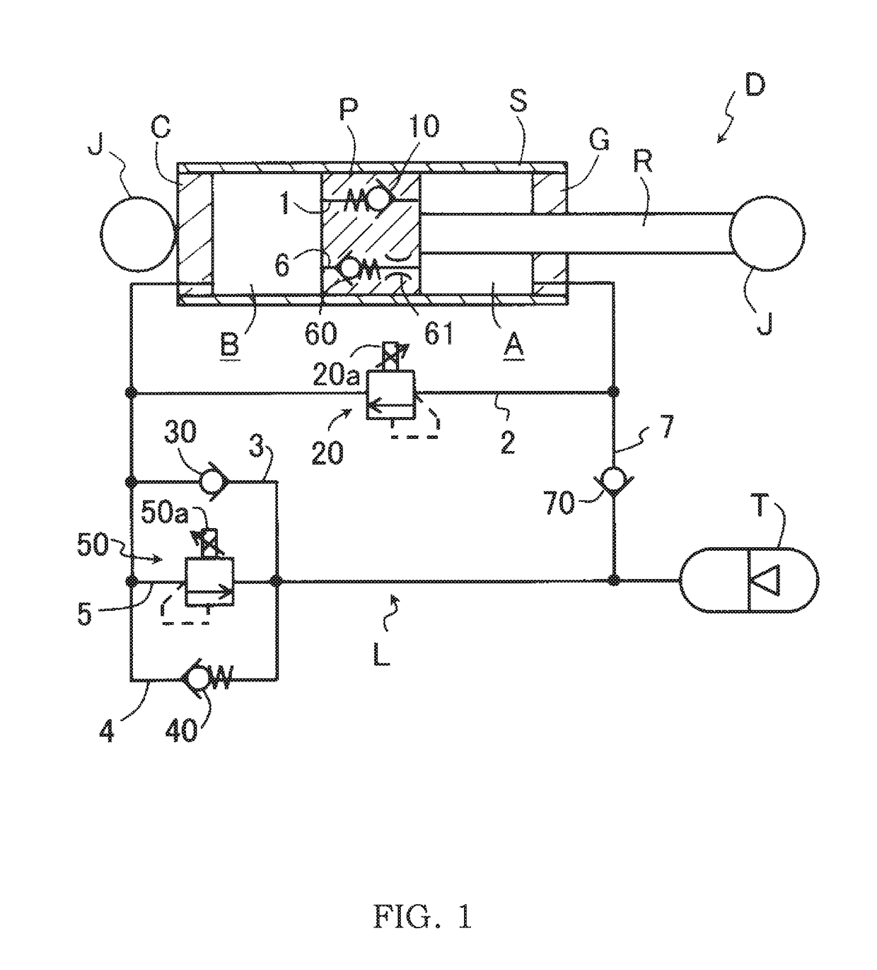
[0015]A shock absorber D according to the present embodiment is used for a rear cushion that suspends a rear wheel of a straddled vehicle, such as a two-wheel vehicle and a three-wheel vehicle. As shown in FIG. 1, the shock absorber D includes a tubular cylinder S, a piston rod R, a piston P, an extension-side chamber A, a compression-side chamber B, a tank T, and passages L. The piston rod R proceeds into and recedes from the cylinder S. The piston P is joined to the piston rod R. The extension-side chamber A and the compression-side chamber B are formed inside the cylinder S, separated from each other by the piston P, and each filled with a working fluid. The tank T is arranged outside the cylinder S and has the working fluid reserved t...


PUM


Abstract

A shock absorber includes a piston joined to a piston rod that proceeds into and recedes from a cylinder, an extension-side chamber and a compression-side chamber that are separated from each other by the piston and have a working fluid reserved therein, first and second extension-side discharge passages in which the working fluid discharged from the extension-side chamber flows, an extension-side supply passage in which the working fluid to be supplied to the compression-side chamber flows, first and second compression-side discharge passages in which the working fluid discharged from the compression-side chamber flows, and a compression-side supply passage in which the working fluid to be supplied to the extension-side chamber flows. An extension-side damping valve and a compression-side damping valve are respectively provided in the first extension-side discharge passage and the first compression-side discharge passage. An extension-side electromagnetic pressure control valve and a compression-side electromagnetic pressure control valve, which are respectively provided in the second extension-side discharge passage and the second compression-side discharge passage, are set such that the openings thereof are maximized before the piston speed reaches a high-speed range.

Description

TECHNICAL FIELD[0001]This invention relates to a shock absorber.BACKGROUND ART[0002]In general, a shock absorber damps vibration of a vehicle, a device, a structure, and the like. JP 2006-183864A discloses a shock absorber for damping vibration associated with the steering of a two-wheel vehicle. This shock absorber includes a tubular cylinder, a fluid chamber, a piston, piston rods, a flow channel, a tank, and a pressure control valve. The fluid chamber is formed inside the cylinder and filled with a working fluid. The piston partitions the fluid chamber into two compartments. The piston rods are provided on both sides of the piston. The two compartments communicate with each other via the flow channel. The tank is connected to an intermediate point of the flow channel and has the working fluid reserved therein. The pressure control valve is provided at an intermediate point of the flow channel. With this shock absorber, no matter which direction the piston moves in, control is per...

Claims


Application Information

Patent Timeline
Patent Type & Authority Patents(United States)
IPC IPC(8): F16F9/512F16F9/516F16F9/50B62K25/28F16F9/19
CPCF16F9/512B62K25/28F16F9/19F16F9/50F16F9/5165F16F2222/12F16F2228/066
Inventor KURITA, NORIHIKO
Owner KYB CORP
Why Eureka
Try Eureka