Apparatus and method for determining a vehicle feature

a vehicle feature and applicator technology, applied in the direction of instruments, measurement devices, using reradiation, etc., can solve the problems of high computing effort and limited measurement accuracy of such radar systems, and achieve the effects of less maintenance, less susceptible to failure, and simple method

Inactive Publication Date: 2017-06-20
KAPSCH TRAFFICCOM AG
View PDF45 Cites 3 Cited by
  • Summary
  • Abstract
  • Description
  • Claims
  • Application Information

AI Technical Summary

Benefits of technology

[0008]It is an object of the disclosed subject matter to create an apparatus and a method for determining a characteristic feature of a vehicle, said apparatus and method being less susceptible to failure and requiring less maintenance than the known optical systems and being simpler, more cost effective and more accurate than the known radar systems.
[0015]The present subject matter is based on the finding of the inventors that the determined frequency spectra reproduce characteristic vehicle features. The vehicle and specific surface structure thereof, such as transitions from body surfaces to glass surfaces, rear-view mirrors, antennas, windscreen wipers, exhaust parts or attached cooling apparatuses etc., each reflect specific spectral components of the transmitted radar beams and thus generate a specific profile of the frequency spectra as a characteristic feature of the vehicle. Changes therein from the first to the second determined frequency spectrum constitute an additional component of the characteristic feature of the vehicle. There is no need for interpretation of each frequency spectrum. This reduces the evaluation effort compared with the known art considerably. In comparison to optical sensors, radar sensors are also less susceptible to the visual impairments occurring in road traffic and are also less susceptible to soiling.
[0016]The direction of the radar beam of the second radar sensor may, for example, be controlled. The second radar sensor can thus be easily adapted to different requirements, for example due to its mounting or with respect to the speed (possibly also the selected lane) of the vehicle; successive radar beams can also be transmitted in different directions.
[0017]The ability to control the direction of the second radar sensor can be achieved, for example, by at least two sequentially controllable radar antennas with different transmission direction; alternatively or in addition, a mechanically pivotable radar antenna could also be used. The second radar sensor may, for example, have a radar antenna with a controllable direction characteristic in the form of a phase-controlled antenna array. There is thus no need for any mechanical movable parts or for a switchover from one radar antenna to another radar antenna; the susceptibility to faults is further reduced, and the availability of the apparatus is increased.
[0029]In an embodiment, the frequency spectra form the characteristic feature as a surface over a frequency / time plane. The surface forms a “fingerprint” of the vehicle so to speak and can be easily stored, compared and even optically evaluated, without further interpretation of the spectral components of the frequency spectra.
[0031]In an embodiment, the current location / time pair may be determined by detection of the current time of part of the vehicle at a predefined current location, wherein the vehicle part is detected by comparing the frequency spectrum of the first reflected radar beam with a reference frequency spectrum determined with an empty roadway. This constitutes a very simple decision criterion for a vehicle detection.

Problems solved by technology

Such systems are reliant on good visibility and are therefore highly dependent on the weather; they often fail in rain, snow or spray.
The measurement accuracy of such radar systems is limited however, and the evaluation of the speeds requires a high computing effort in order to create the traffic flow image.

Method used


Image

  • Apparatus and method for determining a vehicle feature
  • Apparatus and method for determining a vehicle feature
  • Apparatus and method for determining a vehicle feature

Examples


Embodiment Construction

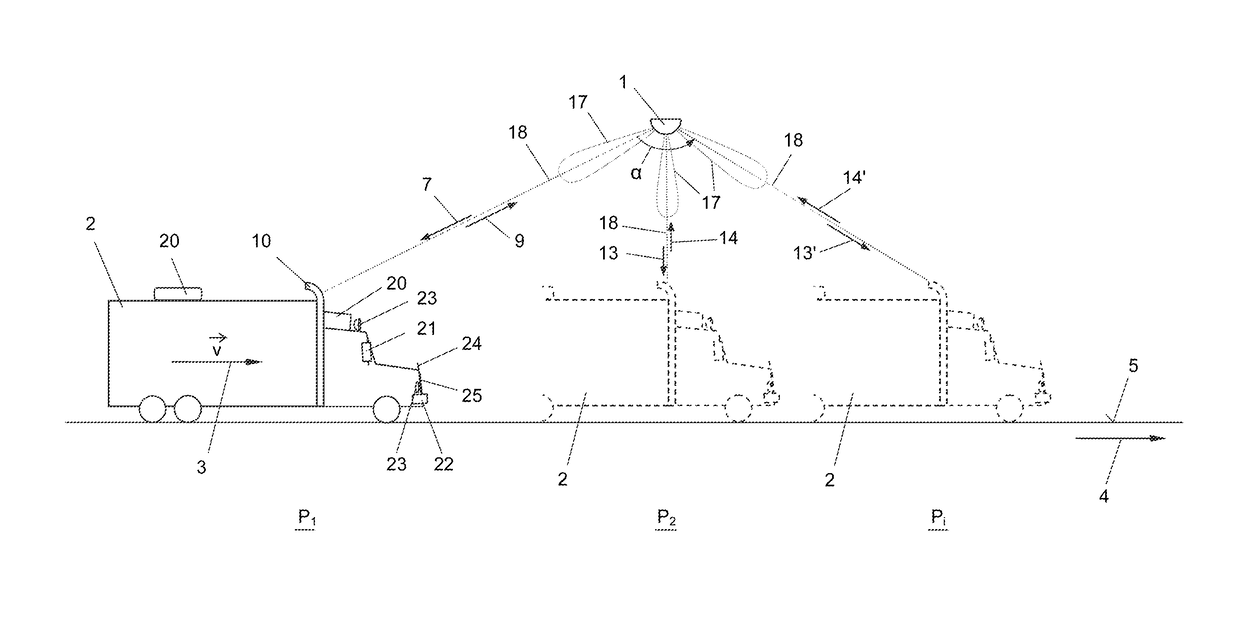
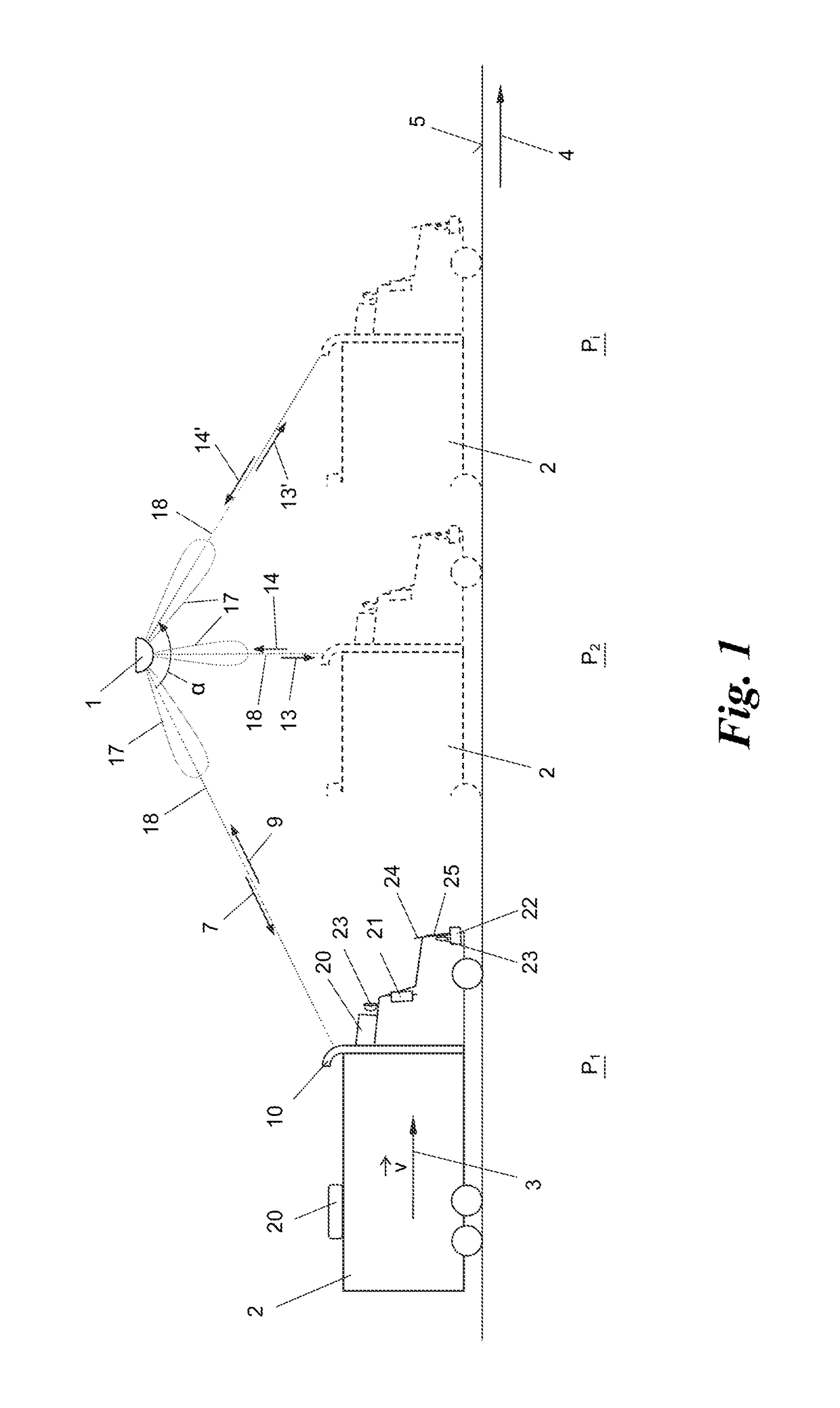
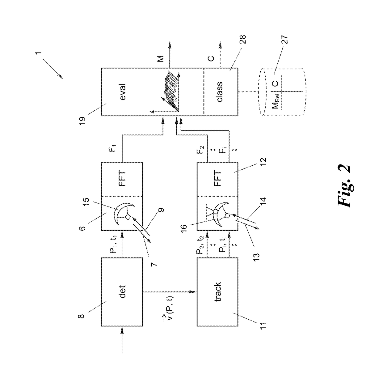
[0038]FIGS. 1 and 2 show an apparatus 1 for determining a characteristic feature M of a vehicle 2, which travels at a speed v along a movement vector 3 in the direction of travel 4 of a roadway 5. A first radar sensor 6 of the apparatus 1 transmits a first radar beam 7, which is directed towards a current location P1 at which the vehicle 2 is detected by a detector 8. The first radar beam 7 is reflected at least in part by the vehicle 2. The first radar sensor 6 then receives a first radar beam 9 reflected on the vehicle 2 and determines a first frequency spectrum F1 thereof in a manner known to a person skilled in the art, for example by means of fast Fourier transformation (FFT).

[0039]The detector 8 detects not only a vehicle 2 at a current location P1 at a current time t1, but also measures the movement vector 3 of the vehicle 2, more specifically before, simultaneously with, or after the transmission of the first radar beam 7. To this end, the detector 8, for example at a curren...


PUM


Abstract

Techniques are disclosed for determining characteristic feature(s) of a vehicle travelling on a roadway, comprising: a detector, which is directed towards the roadway and is configured to measure the movement vector of the vehicle at a current location and time, a tracking unit, connected to the detector, for calculating a target location of the vehicle at a target time on the basis of current location and time and movement vector, a first radar sensor, connected to the detector, for transmitting a radar beam directed towards the current location, receiving a reflected radar beam, and determining a frequency spectrum thereof, a second radar sensor, connected to the tracking unit, for transmitting a radar beam directed towards the target location at the target time, receiving a reflected radar beam and determining a frequency spectrum thereof, and an evaluation unit for generating characteristic feature(s) of the vehicle from the determined frequency spectra.

Description

CROSS-REFERENCE TO RELATED APPLICATION(S)[0001]This application claims priority to European Patent Application No. 13 167 406.1, filed on May 13, 2013, the entirety of which is incorporated by reference herein.BACKGROUND[0002]Technical Field[0003]The present subject matter relates to an apparatus and a method for determining a characteristic feature of a vehicle travelling on a roadway. The present subject matter further relates to a system comprising at least two such apparatuses.[0004]Background Art[0005]The determination of characteristic features of vehicles is important for many tasks in the field of traffic control, traffic monitoring and traffic billing. Individual vehicles can thus be detected and, for example, counted or automatically tracked, assigned on the basis of their features to certain vehicles classes, for example, passenger vehicles or lorries, and class-dependent tariff models or vehicle-class-dependent driving restrictions in road toll systems or parking fee sys...

Claims


Application Information

Patent Timeline
Patent Type & Authority Patents(United States)
IPC IPC(8): G01S7/41G08G1/00G01S13/92G01S13/06G01S13/91G08G1/017G01S13/50G08G1/01G08G1/052
CPCG01S7/41G01S13/06G01S13/91G01S13/92G08G1/01G01S13/50G08G1/017G08G1/0116G08G1/052
Inventor NAGY, OLIVER
Owner KAPSCH TRAFFICCOM AG
Why Eureka
Try Eureka