Connector structure

a technology of connecting structure and connector, applied in the direction of connection, electrical apparatus, coupling device connection, etc., can solve the problem of affecting the efficiency of high frequency signal transmission

Inactive Publication Date: 2017-06-20
P-TWO INDUSTRIES INC
View PDF21 Cites 15 Cited by
  • Summary
  • Abstract
  • Description
  • Claims
  • Application Information

AI Technical Summary

Benefits of technology

[0009]The connector structure of the present invention utilizes the rigid circuit board to replace vertical extending parts of upper and lower terminals of the conventional USB Type-C connector and utilizes the first connecting component whereon the rigid circuit board is inserted to replace pins of u

Problems solved by technology

Furthermore, because super speed signal terminals of the USB type-C connector, when operating, other electronic components might be interfered by the electromagnetic waves, electromagnetic interference (EMI) proof function is nece

Method used


Image

  • Connector structure
  • Connector structure
  • Connector structure

Examples


Embodiment Construction

[0020]In order to illustrate technical specifications and structural features as well as achieved purposes and effects of the present invention, relevant embodiments and figures are described as follows.

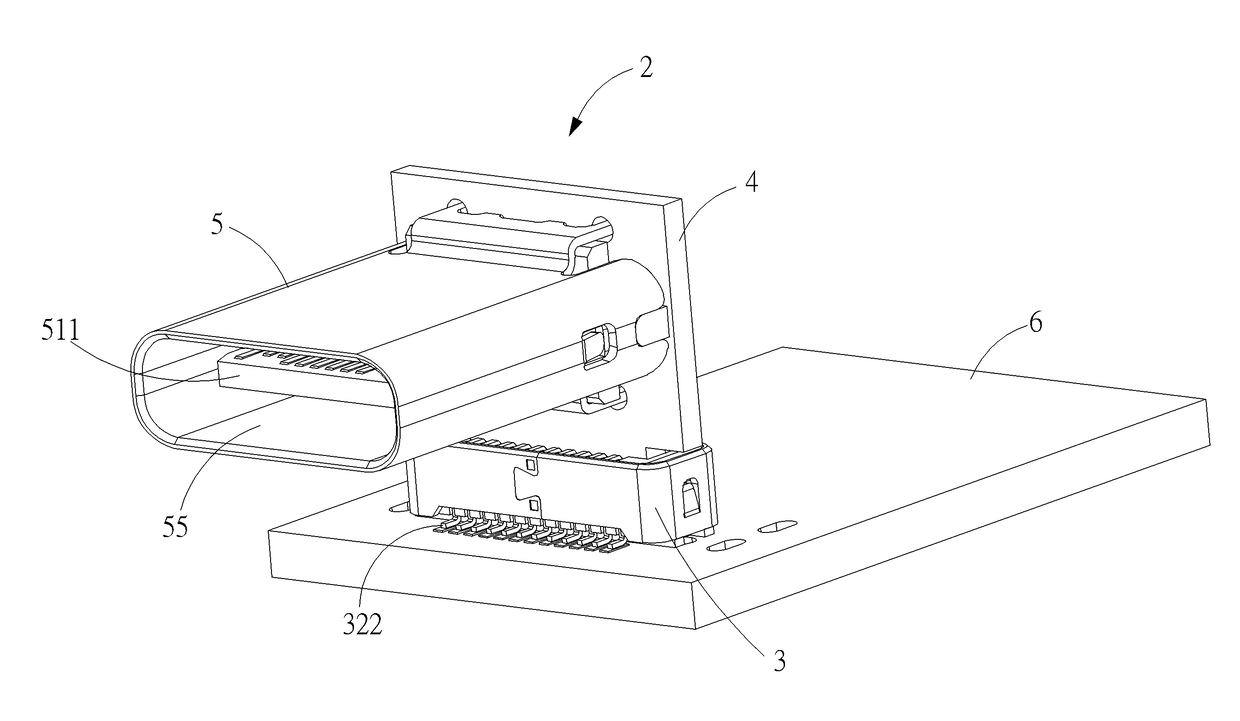
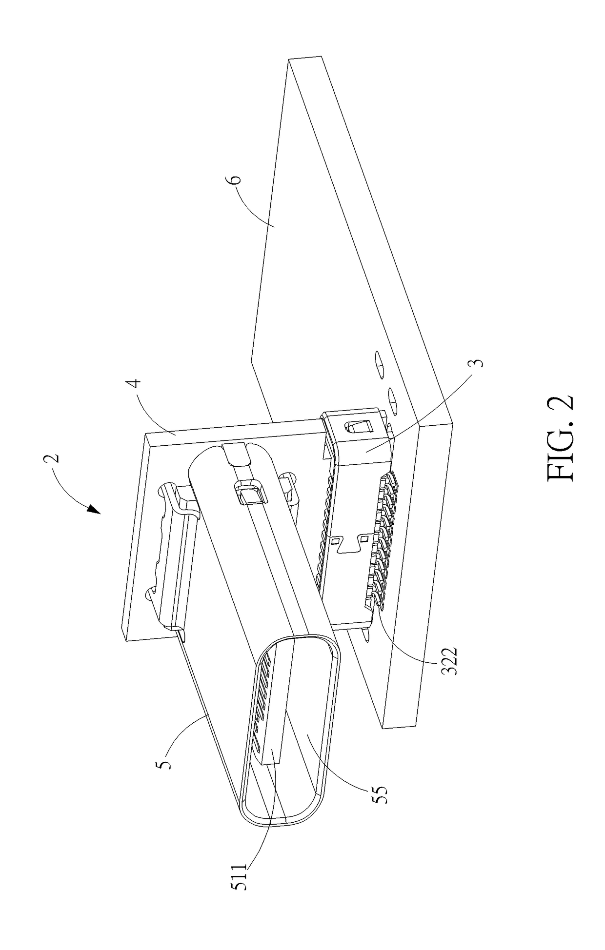
[0021]Please refer to FIG. 2 to FIG. 6. FIG. 2 is a schematic diagram of a connector structure 2 installed on a circuit board 6 according to an embodiment of the present invention. FIG. 3 is a lateral view of the connector structure 2 according to the embodiment of the present invention. FIG. 4 is an exploded diagram of the connector structure 2 according to the embodiment of the present invention. FIG. 5 is an exploded diagram of a second connecting component 5 of the connector structure 2 according to the embodiment of the present invention. FIG. 6 is an exploded diagram of a first connecting component 3 of the connector structure 2 according to the embodiment of the present invention. The connector structure 2 includes the first connecting component 3, a rigid circuit board 4 and ...


PUM


Abstract

A connector structure includes a first connecting component, a rigid circuit board and a second connecting component. The first connecting component includes a first main body whereon a slot is formed, and a plurality of first terminals disposed on the first main body. Each first terminal includes a contacting portion extending into the slot, and a welding portion protruding out of the first main body. The rigid circuit board is assembled into the slot and contacts the contacting portions of the plurality of first terminals. The second connecting component is installed on the rigid circuit board and electrically connected to the plurality of first terminals. The second connecting component includes a second main body, a shielding plate, a plurality of second terminals and a metal shell. The second connecting component, the rigid circuit board and the first connecting component are cooperatively formed in a reverse L-shaped structure.

Description

BACKGROUND OF THE INVENTION[0001]1. Field of the Invention[0002]The present invention relates to a connector structure, and more particularly, to a connector structure applied for high frequency signal transmission.[0003]2. Description of the Prior Art[0004]With rapid development of electronic industries and multimedia application, data transmission between electrical appliances is increasing gradually. Besides expanding transmission bandwidth, the current trend is towards to utilize electrical connectors with high frequency signal transmission. The need for standardization in computer related interfaces, as well as the need for high-speed communication interfaces, leads to the development of the universal serial bus (USB) interface. More recently, the USB Type-C connector has emerged as a USB-type connector having a relatively compact size, ultrahigh data transmission speed, and being configured so that the USB Type-C connector can be coupled without regard to plug orientation and / ...

Claims


Application Information

Patent Timeline
IPC IPC(8): H01R12/00H01R12/57H01R12/71H01R12/52H01R13/6474H01R13/6594
CPCH01R12/52H01R12/716H01R12/57H01R13/6474H01R13/6594H01R12/737H01R13/6473
Inventor WANG, CHIEN-CHUN
Owner P-TWO INDUSTRIES INC
Why Eureka
Try Eureka