Gear transmission
a gear transmission and gear technology, applied in the direction of gearing details, gearing, mechanical equipment, etc., can solve the problems of slow movement speed of the rollers, slow rotation speed of the retainer relative to the case, and sliding of the rollers, so as to reduce the durability of the gear transmission, the abrasion of the rollers is more readily observed, and the carrier is more readily damaged.
- Summary
- Abstract
- Description
- Claims
- Application Information
AI Technical Summary
Benefits of technology
Problems solved by technology
Method used
Image
Examples
embodiments
First Embodiment
[0029]In the embodiment, a gear transmission will be described of a type in which an external gear rotates eccentrically while meshing with an internal gear. A technique taught in the present specification can also be applied to another type of a gear transmission, e.g., a gear transmission in which an internal gear rotates eccentrically while meshing with an external gear. It should be mentioned herein that, in the following description, a retainer making contact with a case via a first member may be expressed simply as “the retainer makes contact with the case”, and the retainer making contact with a carrier via a second member may be expressed simply as “the retainer makes contact with the carrier”.
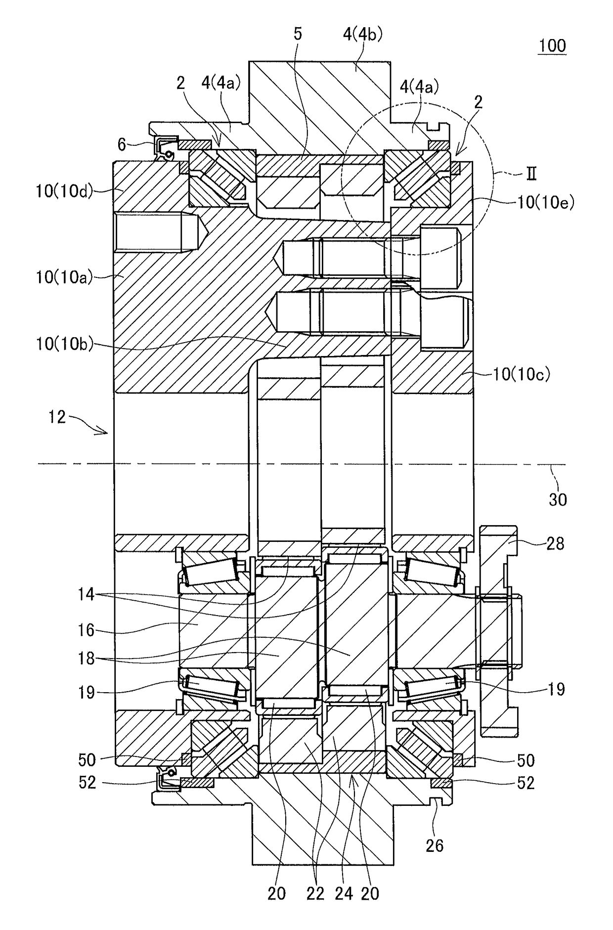
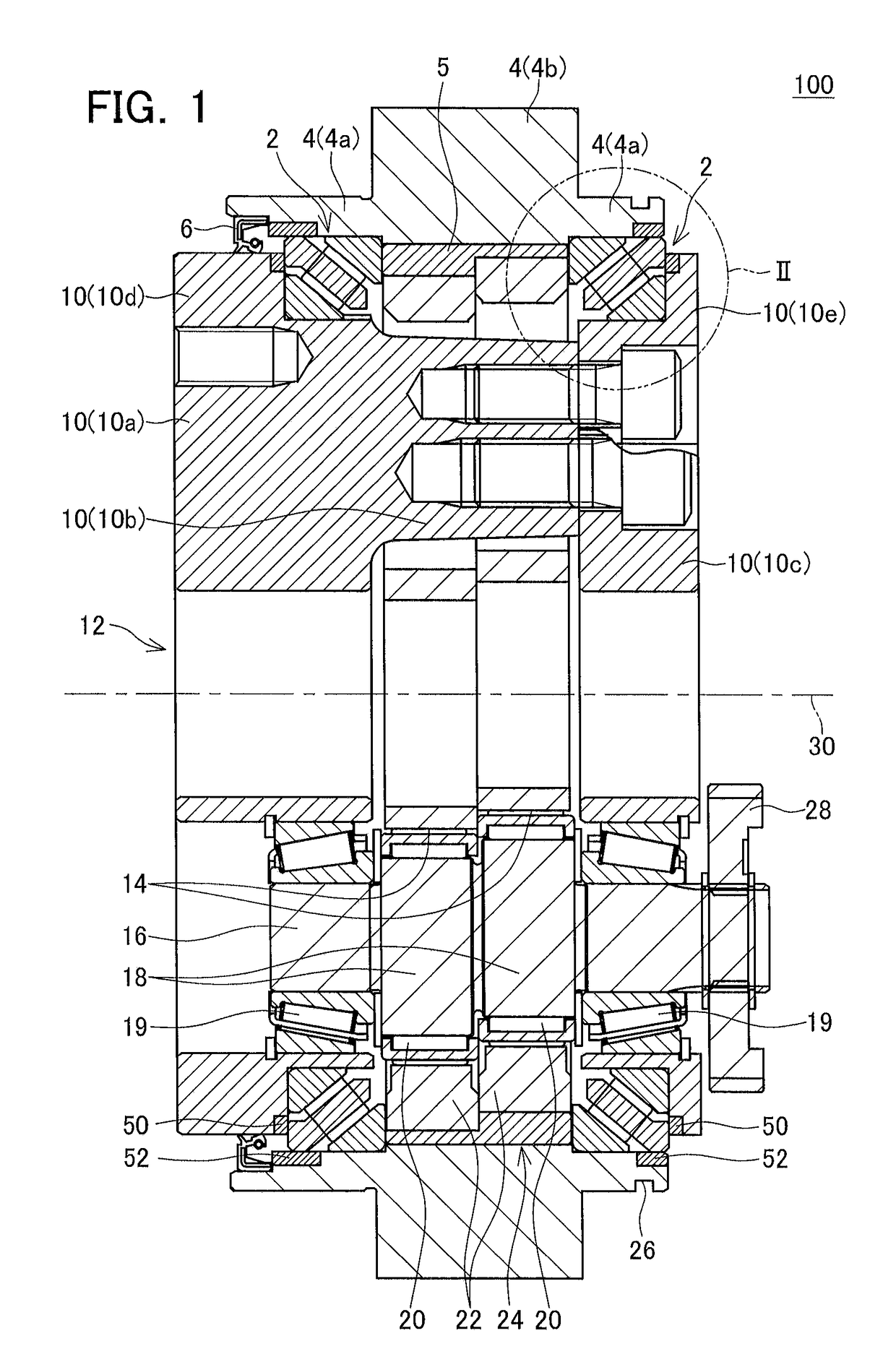
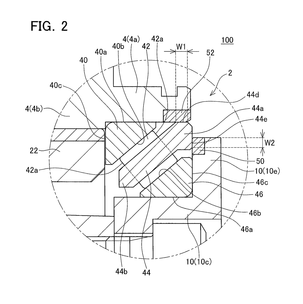
[0030]FIG. 1 shows a cross-sectional view of a gear transmission 100. The gear transmission 100 is an eccentric oscillating type reduction gear. External gears 22 rotate eccentrically while meshing with an internal gear 24. A number of teeth of each of the external gear...
second embodiment
[0058]A gear transmission of a second embodiment will be described with reference to FIGS. 7, 8. The gear transmission of the present embodiment differs from the gear transmission 100 only in a shape of a retainer. Specifically, a retainer 144 of the present embodiment differs from the retainer 44 in a positional relationship of outer circumferential grooves formed in the case contact surface, and end surface grooves formed in the carrier contact surface. Common features of the retainer 144 and the retainer 44 will be denoted by the same reference numbers or by reference numbers having the same lower two digits, and a description thereof may be thereby omitted.
[0059]Outer circumferential grooves 44f and end surface grooves 44g are formed at same positions in a circumferential direction of the retainer 144. Consequently, the outer circumferential grooves 44f and the end surface grooves 44g are contiguous. Lubricant present at the exterior of the cylindrical roller bearings 2 is intro...
third embodiment
[0060]A gear transmission of a third embodiment will be described with reference to FIGS. 9, 10. The gear transmission of the present embodiment differs from the gear transmission 100 only in a shape of a retainer. Specifically, a retainer 244 of the present embodiment differs from the retainer 44 in a shape of outer circumferential grooves formed in the case contact surface, and a shape of end surface grooves formed in the carrier contact surface. Common features of the retainer 244 and the retainer 44 will be denoted by the same reference numbers or by reference numbers having the same lower two digits, and a description thereof may be thereby omitted.
[0061]As shown in FIG. 9, a plurality of end surface grooves 244g is formed in a carrier contact surface 244e. When the end surface grooves 244g are viewed along the bearing center axis 30 direction, a direction along which the end surface grooves 244g extend is inclined with respect to a straight line joining an outer peripheral sur...
PUM
 Abstract
Description
Claims
Application Information
 - R&D
- Intellectual Property
- Life Sciences
- Materials
- Tech Scout
- Unparalleled Data Quality
- Higher Quality Content
- 60% Fewer Hallucinations
Browse by: Latest US Patents, China's latest patents, Technical Efficacy Thesaurus, Application Domain, Technology Topic, Popular Technical Reports.
© 2025 PatSnap. All rights reserved.Legal|Privacy policy|Modern Slavery Act Transparency Statement|Sitemap|About US| Contact US: help@patsnap.com


