
Power-generating system having a fuel cell

a fuel cell and power-generating system technology, applied in the direction of cell components, electrochemical generators, emergency supply, etc., can solve the problem of long period of inactivity of power-generating systems

Active Publication Date: 2017-06-27
AREVA STOCKAGE DENERGIE
View PDF14 Cites 0 Cited by
  • Summary
  • Abstract
  • Description
  • Claims
  • Application Information

AI Technical Summary

Benefits of technology

This patent describes a system and method for generating power using a fuel and oxidizer. The system includes an energy storage device that maintains a high level of energy to start the power generation assembly when needed. The technical effect of this system is to allow for efficient and reliable power generation even when the energy levels in the fuel and oxidizer are low.

Problems solved by technology

Such power-generating systems are inactive for long periods of time.

Method used


Image

  • Power-generating system having a fuel cell
  • Power-generating system having a fuel cell

Examples


Embodiment Construction

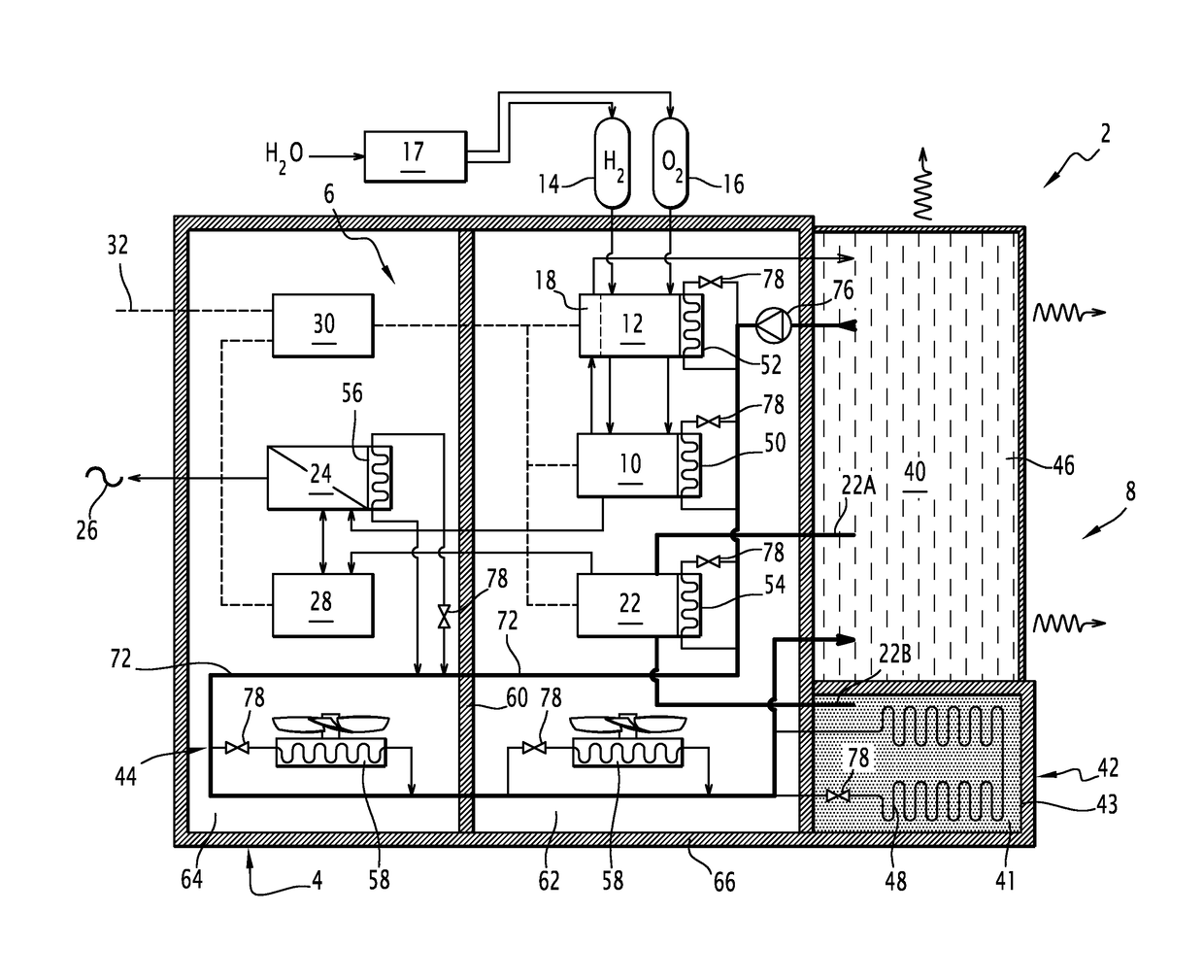
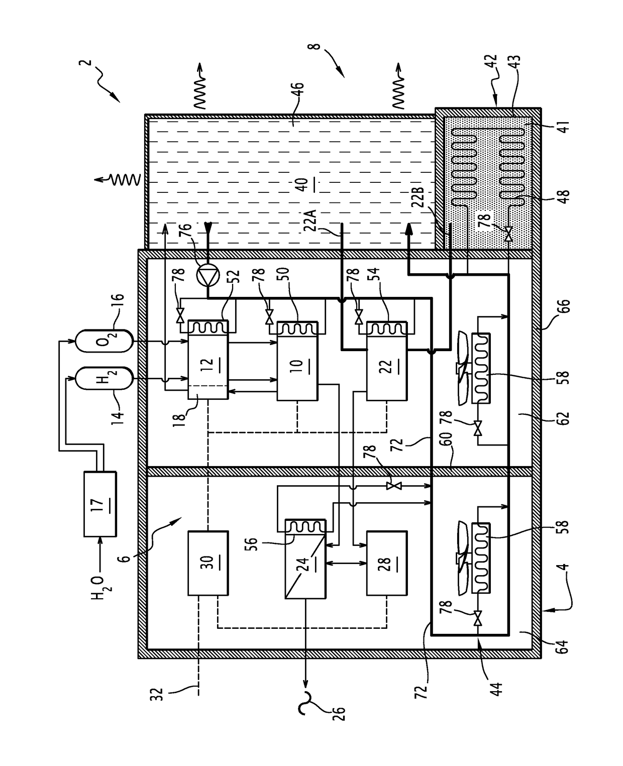
[0035]The power-generating system 2 illustrated in the figure comprises a tight chamber 4, an electricity-generating assembly 6 comprising power-generating equipment positioned inside the chamber 4, and a heat control system 8 to control the temperature of the electricity-generating assembly 6.

[0036]The chamber 4 is configured to be tight with respect to gaseous or liquid fluids. The chamber 4 delimits a closed and fluid-tight inner volume.

[0037]The electricity-generating assembly 6 is positioned inside the chamber 4. Each piece of functional equipment of the electricity-generating assembly 6 is positioned inside the chamber 4.

[0038]The electricity-generating assembly 6 comprises a fuel cell 10 for producing power by means of an oxidation-reduction reaction between an oxidizer and a fuel. The fuel cell 10 is positioned inside the chamber 4.

[0039]The fuel cell 10 comprises at least one electrochemical cell, and preferably several stacked electrochemical cells forming a stack or a set...


PUM

PropertyMeasurementUnit
temperatureaaaaaaaaaa

Abstract

A power-generating system is provided including a fluid-tight chamber and an electricity-generating assembly arranged in the chamber, the electricity-generating assembly comprising a fuel cell for generating power by means of an oxidation-reduction reaction between an oxidizer and a fuel, and a supply system for supplying oxidizer and fuel to the fuel cell, the power-generating system also including a heat-control system including a cold source and a hot source, and a heat-transport fluid circuit that is configured to control the temperature of the electricity-generating assembly by exchanging heat with the cold source and the hot source.

Description

[0001]The present invention relates to power-generating systems having a fuel cell that produces electricity by oxidation-reduction of a fuel and an oxidizer.[0002]Such power-generating systems are used as backup power sources in case of failure of the electric grid, to supply power to buildings or sensitive facilities requiring continuous operation for at least some of their equipment, such as a hospital or nuclear power plant. A failure in the electric grid may for example be caused by a natural disaster, such as a flood, earthquake, meteorological event (cyclone, typhoon, tornado, etc.).BACKGROUND[0003]Such power-generating systems are generally sized to provide backup electricity over a long length of time from several hours to several days.[0004]Such power-generating systems are inactive for long periods of time. The environment in which they must operate is not known in advance (temperature, atmospheric pollution, radiation, flood, etc.).SUMMARY OF THE INVENTION[0005]It is des...

Claims


Application Information

Patent Timeline
Patent Type & Authority Patents(United States)
IPC IPC(8): H01M16/00H01M8/2475H01M8/04029H01M8/1018H01L35/30H01M8/04007H01M8/241H01M8/2425H01M8/1246H01M8/124H10N10/13
CPCH01M16/003H01L35/30H01M8/04029H01M8/04052H01M8/04074H01M8/1018H01M8/1246H01M8/241H01M8/2425H01M8/2475H01M16/006H01M2008/1095H01M2008/1293H01M2250/10H01M2250/402H01M2300/0074H01M2300/0082Y02B90/12Y02B90/14Y10T307/658H01M8/04268H01M8/04225Y02B90/10Y02E60/50Y02E60/10H01M8/04302H10N10/13
Inventor CHAUDRON, VALERY
Owner AREVA STOCKAGE DENERGIE
Learn More