Auxiliary bearing for magnetically suspended rotor system

a technology of auxiliary bearings and rotors, which is applied in the direction of magnetic bearings, sliding contact bearings, mechanical equipment, etc., can solve the problems of insufficient load carrying capacity of sleeves, high cost of bearings, and inability to handle high sliding speeds, so as to reduce wear and damage of sleeves

Active Publication Date: 2017-07-04
AB SKF +1
View PDF13 Cites 1 Cited by
  • Summary
  • Abstract
  • Description
  • Claims
  • Application Information

AI Technical Summary

Benefits of technology

[0014]The technical problem to be solved is therefore to remedy the above-mentioned drawbacks and in particular to reduce the wear and damage of a sleeve and a bushing of an auxiliary bearing of the sleeve-bushing type during failure of an associated magnetic bearing or when a shaft supported by an associated magnetic bearing is brought to rest.
[0048]The logarithmic profile results in less height deviation in the center, while giving more height deviation at the ends of the sleeve, which gives more sensitivity to misalignment but reduces contact pressure in the nominal situation.

Problems solved by technology

However such bearings are very costly and moreover require a lot of space.
In particular sleeves have typically insufficient load carrying capacity and cannot handle high sliding speeds.
Due to the air gap of the magnetic bearing, it cannot be predicted if the shaft will drop in such a way that it is axially aligned with the center axis of the bushing.
It could happen that the shaft and the bushing are misaligned instead of being coaxial.
This creates very high contact pressures on the edges of the sleeve which is mounted on the shaft.
Under such circumstances, a very high degree of unbalance can arise leading to destruction of the bearings or to deformation of the rotor.

Method used


Image

  • Auxiliary bearing for magnetically suspended rotor system
  • Auxiliary bearing for magnetically suspended rotor system
  • Auxiliary bearing for magnetically suspended rotor system

Examples


Embodiment Construction

[0060]The present invention will be described in connection with preferred embodiments which are given by way of examples.

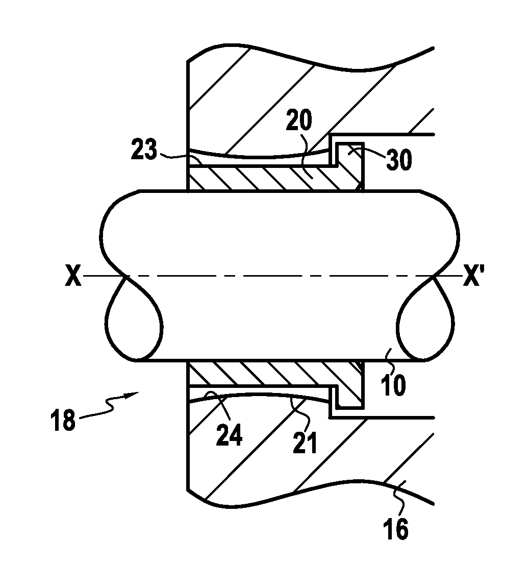
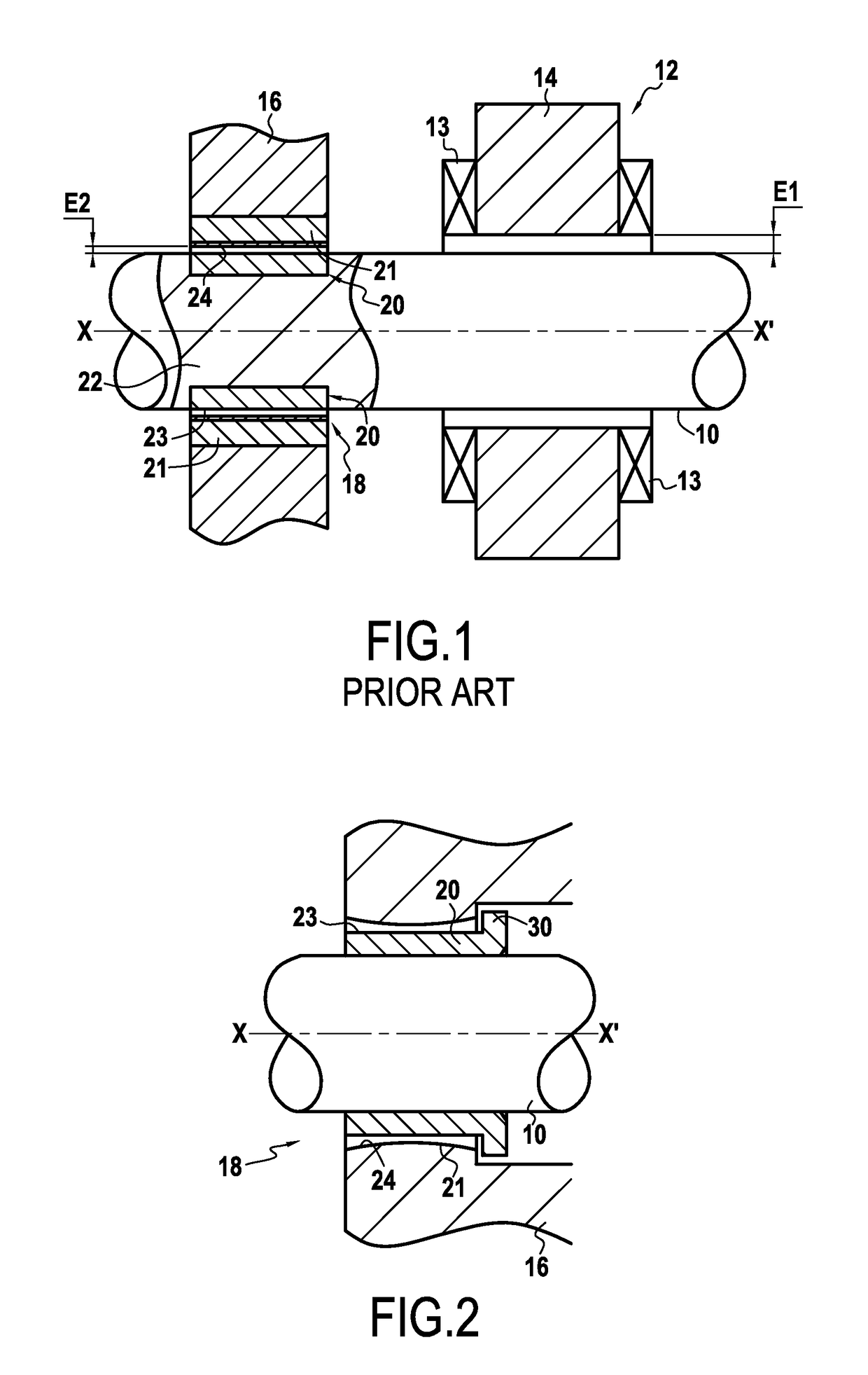
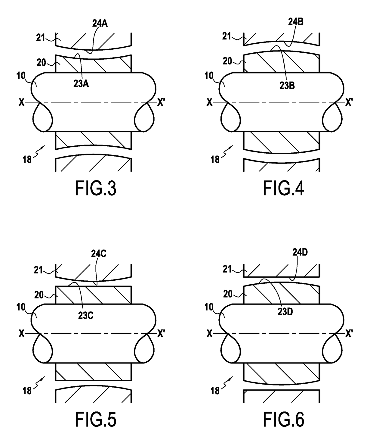
[0061]As already mentioned, FIG. 1 shows a typical arrangement of an assembly comprising a radial magnetic bearing 12 defining an air gap E1 and of an auxiliary bearing 18 having a bushing 21 and a sleeve 20 defining a clearance E2 there between which is less than the mean air gap E1. During normal operation, the shaft 10 is supported by the magnetic bearing 12 without contact with the stator 13, 14 of the magnetic bearing 12 and with the bushing 21 of the auxiliary bearing 18, whereas in case of a failure in the operation of the magnetic bearing 12, such as a power failure, the sleeve 20 of the shaft 10 lands on the bushing 21 of the auxiliary bearing 18. When the sleeve 20 and bushing 21 both have the same conventional cylindrical shape with a symmetry around the longitudinal axis of the shaft 10 whilst having the same straight profile in a longitudinal cross-s...


PUM


Abstract

An assembly that includes a rotating shaft supported with respect to a stationary housing by at least one active magnetic bearing presenting a mean radial air gap and at least one auxiliary bearing having a bushing fixed to the housing and a sleeve fixed on the rotating shaft. The bushing and the sleeve have opposite surfaces that define a clearance (E2) which is less than the mean radial air gap (E1). The bushing and the sleeve each exhibit symmetry around a longitudinal axis of the shaft and have different profiles in a longitudinal cross-section including the longitudinal axis to optimize the contact pressure distribution when the rotating shaft lands on the auxiliary bearing.

Description

CROSS-REFERENCE TO RELATED APPLICATIONS[0001]This application claims priority to European Patent Application EP13305701.8 filed May 29, 2013, which is herein fully incorporated by reference.FIELD OF THE INVENTION[0002]The present invention relates to an auxiliary bearing for a magnetically suspended rotor system and to a magnetic suspension incorporating such auxiliary bearing.BACKGROUND OF THE INVENTION[0003]Magnetic bearings operate without mechanical friction, but require continuous supply with electrical power. In case of a power failure, the shaft needs to be supported by a so-called auxiliary bearing, which is also called landing bearing, emergency bearing or back-up bearing.[0004]Thus rotary machines equipped with active magnetic bearings include mechanical auxiliary bearings which act if one of the magnetic bearings is overloaded or if the electrical or electronic control circuit fails or else in the event of stoppage or of suspension overload.[0005]An auxiliary device provi...

Claims


Application Information

Patent Timeline
Patent Type & Authority Patents(United States)
IPC IPC(8): F16C32/04F16C33/06F16C39/02F16C23/04H02K7/09
CPCF16C32/0402F16C23/041F16C32/047F16C32/0442F16C32/0474F16C33/06F16C39/02F16C2240/40F16C2360/44H02K7/09F16C2240/50
Inventor KREBS, PHILIPPANDERS, JENSHERISSE, EDDYPONSON, FREDERIC
Owner AB SKF
Why Eureka
Try Eureka