Method and magnetic resonance apparatus for image acquisition

a magnetic resonance apparatus and image acquisition technology, applied in the field of image acquisition, can solve problems such as measurement errors, and achieve the effect of improving contrast and signal-to-noise ratio

Active Publication Date: 2017-07-04
SIEMENS HEALTHCARE GMBH
View PDF24 Cites 0 Cited by
  • Summary
  • Abstract
  • Description
  • Claims
  • Application Information

AI Technical Summary

Benefits of technology

[0019]Typical magnetic resonance sequences of this type—in particular PETRA sequences—have two measurement segments in which, initially, the first region of k-space is measured (radial scan), whereupon the Cartesian scan takes place in a second region of k-space in a further measurement segment. A number of spokes—for example several tens of thousands of spokes—are thereby designated to be filled with data in order to design the back-calculation (regridding) to a Cartesian grid in k-space so as to have as few errors as possible before a reconstruction of the image data from the raw data. The typical procedure (as described above) is that a specific, fixed number of repetitions are measured after each administration of pre-pulse (and a corresponding first wait time TVP), which means that the entire measurement process with its Nges measurement processes (repetitions) is subdivided by the pre-pulses into sub-segments, such that at which point in time the center of k-space is measured is ultimately random. The method according to the invention improves this procedure by adapting the described procedure in the MPRAGE sequence to the PETRA sequence, and the characteristics of the PETRA acquisition are optimally utilized. If (as already described) it is assumed that the two measurement segments are present, in accordance with the present invention a targeted, minimal increase or decrease of the number of radial spokes to be measured is determined, in order to shift the point in time at which the center of k-space is measured to the optimal acquisition point in time (as has already been noted with regard to the general description of the prior art). An optimal point in time (defined by a time TI after the pre-pulse) is thus determined during the relaxation after a pre-pulse (as is known in the prior art), and the number of radial spokes is specifically, minimally modified after this specification of the optimal point in time. Decisive advantages result from this, namely stabilization of the contrast, better modulation of the contrast, and an optimal agreement between contrast and signal-to-noise ratio (SNR). The method is applicable to different pre-pulses, in particular also to T2 pre-pulses at desired T2 contrasts.
[0022]It is advantageous to determine an actual number of spokes to be measured from a user specification of the number of spokes to be measured. Because the basic workflow of the complete magnetic resonance sequence is known, in particular with regard to the points in time and the subsequent measurement processes (repetitions), a small (in terms of percentage) correction that shifts the measurement of the k-space center to the optimal point in time can be applied automatically from a number of radial spokes that are predetermined by the system or according to a desire chosen by a user. A correction that is barely detectable or completely undetectable by the user is consequently made that leads to a markedly improved quality of the image acquisition with regard to the contrast and the signal-to-noise ratio.

Problems solved by technology

Such jumps can also lead to measurement errors.

Method used


Image

  • Method and magnetic resonance apparatus for image acquisition
  • Method and magnetic resonance apparatus for image acquisition
  • Method and magnetic resonance apparatus for image acquisition

Examples


Embodiment Construction

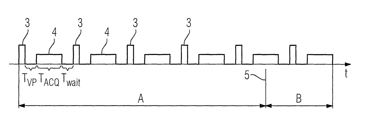
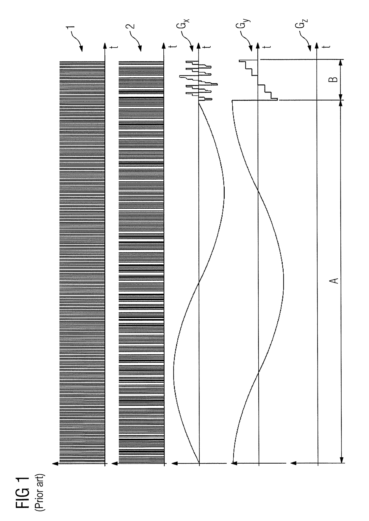
[0033]FIG. 1 shows the workflow of a PETRA sequence as a magnetic resonance sequence, as is known in the prior art (for example DE 10 2010 041 446 A1, corresponding to U.S. Pat. No. 8,887,533), and that can be used for image acquisition in a magnetic resonance device. The first line in FIG. 1 shows the radiated radio-frequency excitation pulses 1; the second line shows the associated readout time periods 2. The excitation pulses 1 are respectively repeated at an interval of a repetition time TR which remains constant across the entire sequence. In the present exemplary embodiment, two phase coding gradients Gx and Gy are switched, such that a coding in the third direction (the slice direction, here the z-direction) is foregone (Gz=0).

[0034]If scanning takes place both in a first measurement segment A in which a first region of k-space is scanned radially along spokes and in a second measurement segment B in which the second region of k-space (that is not included by the first region...


PUM


Abstract

In a method and magnetic resonance apparatus for image acquisition using a magnetic resonance sequence in which k-space corresponding to the imaging area is scanned, a first region of k-space, which does not include the center of k-space, is scanned radially along a number of spokes emanating from the k-space center, and at least two phase coding gradients are completely ramped up before the excitation pulse. A second central region of k-space, which remains without the first region, is scanned in a Cartesian manner. For contrast increase a pre-pulse is provided before a predetermined number of individual measurements. The number of spokes is selected so a measurement point nearest to the k-space center is measured at a predetermined point in time after the pre-pulse, which is optimal for signal-to-noise ratio and / or contrast.

Description

BACKGROUND OF THE INVENTION[0001]Field of the Invention[0002]The invention concerns a method for image acquisition with a magnetic resonance device using a magnetic resonance sequence (in particular a PETRA sequence) of the type wherein k-space corresponding to the imaging area is scanned, with a first region of k-space that does not include the center of k-space being scanned radially along a number of spokes emanating from the center of k-space, and wherein at least two phase coding gradients have already been ramped up completely before administration of the excitation pulse; and wherein a second central region of k-space that remains without the first region is scanned in a Cartesian manner (in particular via single point imaging), with a pre-pulse (in particular an inversion pulse to establish a T1 contrast) being radiated before a predetermined number of individual measurements for the purpose of increasing the contrast. The invention also concerns a magnetic resonance apparat...

Claims


Application Information

Patent Timeline
Patent Type & Authority Patents(United States)
IPC IPC(8): G01V3/00G01R33/48G01R33/56A61B5/055
CPCG01R33/482G01R33/4816G01R33/5602A61B5/055
Inventor GRODZKI, DAVID
Owner SIEMENS HEALTHCARE GMBH
Why Eureka
Try Eureka