Pulsatile orthodontic device and methods

a technology of pulsatile and orthodontics, applied in the field of pulsatile devices, can solve the problems of reducing usage and compliance, complicated orthodontic treatment, and long treatment time of 24 months, and achieve the effect of faster tooth movement rate and faster method of orthodontic remodeling

Active Publication Date: 2017-07-11
ADVANCED ORTHODONTICS & EDUCATION ASSOC LLC
View PDF15 Cites 26 Cited by
  • Summary
  • Abstract
  • Description
  • Claims
  • Application Information

AI Technical Summary

Benefits of technology

[0036]Preferably, a custom or semi-custom application-specific integrated circuit (ASIC) is designed to drive the device, and is particularly preferred for a completely intraoral device. An ASIC can include entire microprocessors, memory blocks including ROM, RAM, EEPROM, Flash and other large building blocks. Such an ASIC is often termed a SoC (system-on-chip). Hardware description language (HDL), such as Verilog or VHDL, can be used to describe the functionality of ASICs. Field-programmable gate arrays (FPGA) are another option for driving the device. Programmable logic blocks and programmable interconnects allow the same FPGA to be used in many different applications. For smaller designs and / or lower production volumes, FPGAs may be more cost effective than an ASIC design even in production.
[0068]In another embodiment, what is provided is a faster method of orthodontic remodeling, comprising: a patient wearing braces or an aligner biting the bite plate of the orthodontic remodeling device as herein described, and activating said orthodontic remodeling device for about 20 minutes daily, wherein a tooth movement rate is faster with usage of said orthodontic remodeling device than it is without usage of said orthodontic remodeling device.

Problems solved by technology

Any variations therefrom results in malocclusion.
Orthodontic treatment is complicated by the fact that it is uncomfortable and / or painful for patients, and the orthodontic appliances are perceived as unaesthetic, all of which creates resistance to use.
Further, the 24-month treatment time is very long, and further reduces usage and compliance, which can include chronic poor dental hygiene.
However, this idea did not become practical until the advent of 3D scanning and computer modeling in 1997.
However, because these appliances can be removed, compliance can be an issue, and failure to use slows overall treatment time.
As a treatment modality, aligners are also limited in the classifications of clinical malocclusion that they can address.
In the past, aligners have not been able to easily rotate or extrude teeth because the aligner cannot adequately direct force in all directions.
The early Mao studies provided a basis for both possible efficacy and likely safety for using pulsatile forces or vibration in humans to assist orthodontic tooth movement, but the experiments needed to be repeated with humans and with teeth and no plausible device existed.
Finally, the device is slim, capable of hands free operation, lacks the bulky head gear of the prior art devices, and has optimized force and frequency for orthodontic remodeling.

Method used


Image

  • Pulsatile orthodontic device and methods
  • Pulsatile orthodontic device and methods
  • Pulsatile orthodontic device and methods

Examples


Embodiment Construction

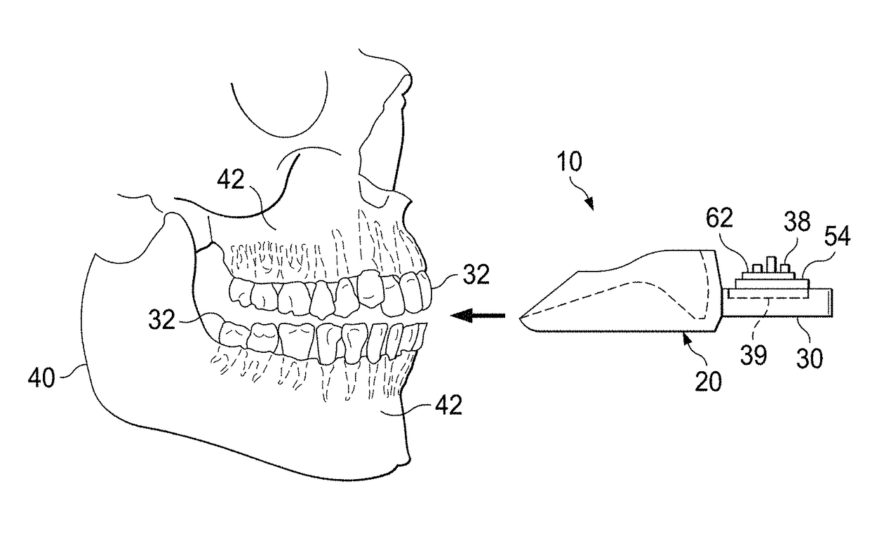
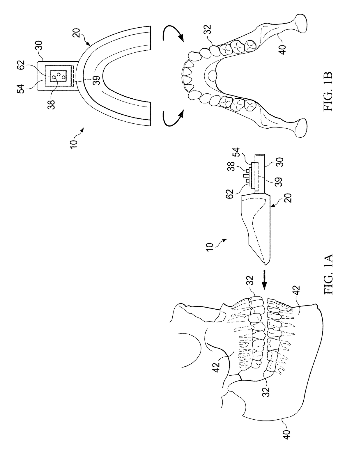
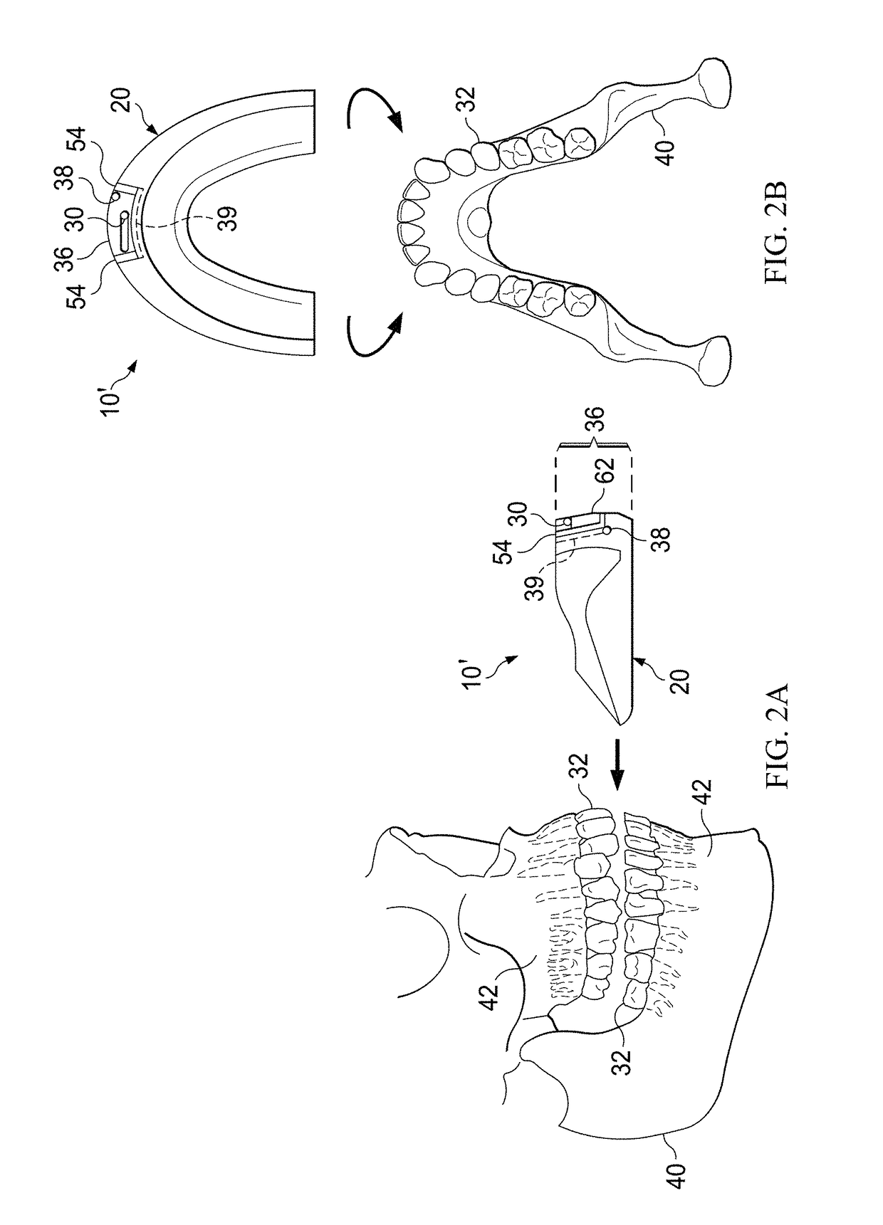
[0094]In accordance with one embodiment of the invention, non-static forces (e.g., vibration) are used to accelerate the remodeling of craniofacial bones in conjunction with orthodontic treatment. The system can be used to treat all forms and classifications of dental malocclusion, craniofacial anomaly, boney defect, or dentofacial deformity in which bone remodeling plays a physiological role. The system can be used exclusively in the maxilla, exclusively in the mandible, or in a dual-arch manner (both maxilla and mandible at the same time). Furthermore, the system can be used to treat cases presenting with a full dentition, any combination of naturally or unnaturally missing teeth, and to remodel bone in edentulous patients. Patients of any age and medical history profile can be treated. The system can be used by patients taking any type of medication.

[0095]FIG. 1A-B shows one embodiment of an orthodontic device 10. The device 10 has an intraoral bite plate 20 that is inserted into...


PUM


Abstract

Orthodontic remodeling devices having an extraoral housing containing a power source operably coupled to an actuator operably coupled to a processor that controls said actuator; the extraoral housing operably connected to an intraoral U-shaped bite plate; the bite plate having upper and lower vertical edges on a facial edge thereof and upper and lower vertical edges on a lingual edge thereof. During usage the orthodontic remodeling device is held in place only by teeth clamping on the bite plate and vibrates at a selected frequency between 0.1 and 400 Hz. Methods of using same for faster orthodontic remodeling and pain reduction are also provided.

Description

PRIOR RELATED APPLICATIONS[0001]This application is a Continuation-in-Part (CIP) of U.S. Provisional Application Ser. No. 60 / 906,807, filed on Mar. 14, 2007, Ser. No. 11 / 773,849 (published as US20080227046, pending), filed Jul. 5, 2007, Ser. No. 13 / 609,346 filed Sep. 11, 2012 (pending), Ser. No. 13 / 684,220 filed Nov. 22, 2012 (issued as U.S. Pat. No. 8,500,446) and Ser. No. 13 / 973,865 filed Aug. 22, 2013 (issued as U.S. Pat. No. 8,939,762).[0002]The application is also a CIP of 60 / 906,807, filed Mar. 14, 2007, Ser. No. 12 / 615,049 (issued as U.S. Pat. No. 9,028,250), filed Nov. 9, 2009, as well as Ser. No. 14 / 612,121 (US20150173857, pending) and Ser. No. 14 / 612,127 (US2015147711, pending), both filed Feb. 2, 2015.[0003]This application is also a CIP of U.S. application Ser. No. 13 / 609,346 (US2014272761 pending), filed Sep. 11, 2012, Ser. No. 13 / 684,220 (issued as U.S. Pat. No. 8,500,446), filed Nov. 22, 2012, and Ser. No. 13 / 973,865 (issued as U.S. Pat. No. 8,939,762), filed Aug. 22,...

Claims


Application Information

Patent Timeline
Patent Type & Authority Patents(United States)
IPC IPC(8): A61C3/00A61C7/00A61C7/08A61C1/00
CPCA61C7/008A61C7/00A61C7/002A61C7/08A61C1/0015A61C2204/002A61C2204/005
Inventor LOWE, MICHAEL K.
Owner ADVANCED ORTHODONTICS & EDUCATION ASSOC LLC
Why Eureka
Try Eureka