Eureka AIR delivers breakthrough ideas for toughest innovation challenges, trusted by R&D personnel around the world.

Rooster boot ankle foot orthosis

a technology for ankles and boots, applied in the field of ankle foot orthosis, can solve the problems of generalized confronted with muscle imbalance, imbalance of muscle pulls, and misalignment of involved joints, and achieve the effects of preventing spastic contracture shortening of heel cord, preventing sprain of heel cord, and optimum security and stability

Active Publication Date: 2017-07-18
MEYER GRANT C
View PDF17 Cites 8 Cited by
  • Summary
  • Abstract
  • Description
  • Claims
  • Application Information

AI Technical Summary

Benefits of technology

The present invention is a lightweight orthosis designed to be worn at night and during rest to increase the range of motion and correct the alignment of the foot and ankle complex. It provides adjustable dynamic stretch load to the posterior muscles and heel cord to prevent contracture and shortening of the heel cord. The orthosis is designed to hold the patient's corrected shape contours independent from the outer shell and foot shell, and it promotes a low-load stretch during rest and sleep to improve the patient's range of motion. It is non-cumbersome, light-weight, and provides circumferential support and dynamic stabilizing forces while maintaining a corrected alignment of the bones of the foot and ankle. It also includes monitoring and control features and is utilized during weight bearing use.

Problems solved by technology

Children having spasticity, a condition often scene in cerebral palsy and similar types of medical disorders, are generally confronted with muscle imbalance, as their muscles do not work together in the manner of non-spastic children.
This imbalance of muscle pulls and involuntary forces, usually called spastic contractures, creates misalignment of involved joints.
If this misalignment is not corrected and range of motion restored, it will eventually lead to permanent deformity as the child ages.
This shortened heel cord can generate additional undesirable positions, which can lead to permanent deformity if not treated.

Method used


Image

  • Rooster boot ankle foot orthosis
  • Rooster boot ankle foot orthosis
  • Rooster boot ankle foot orthosis

Examples


Embodiment Construction

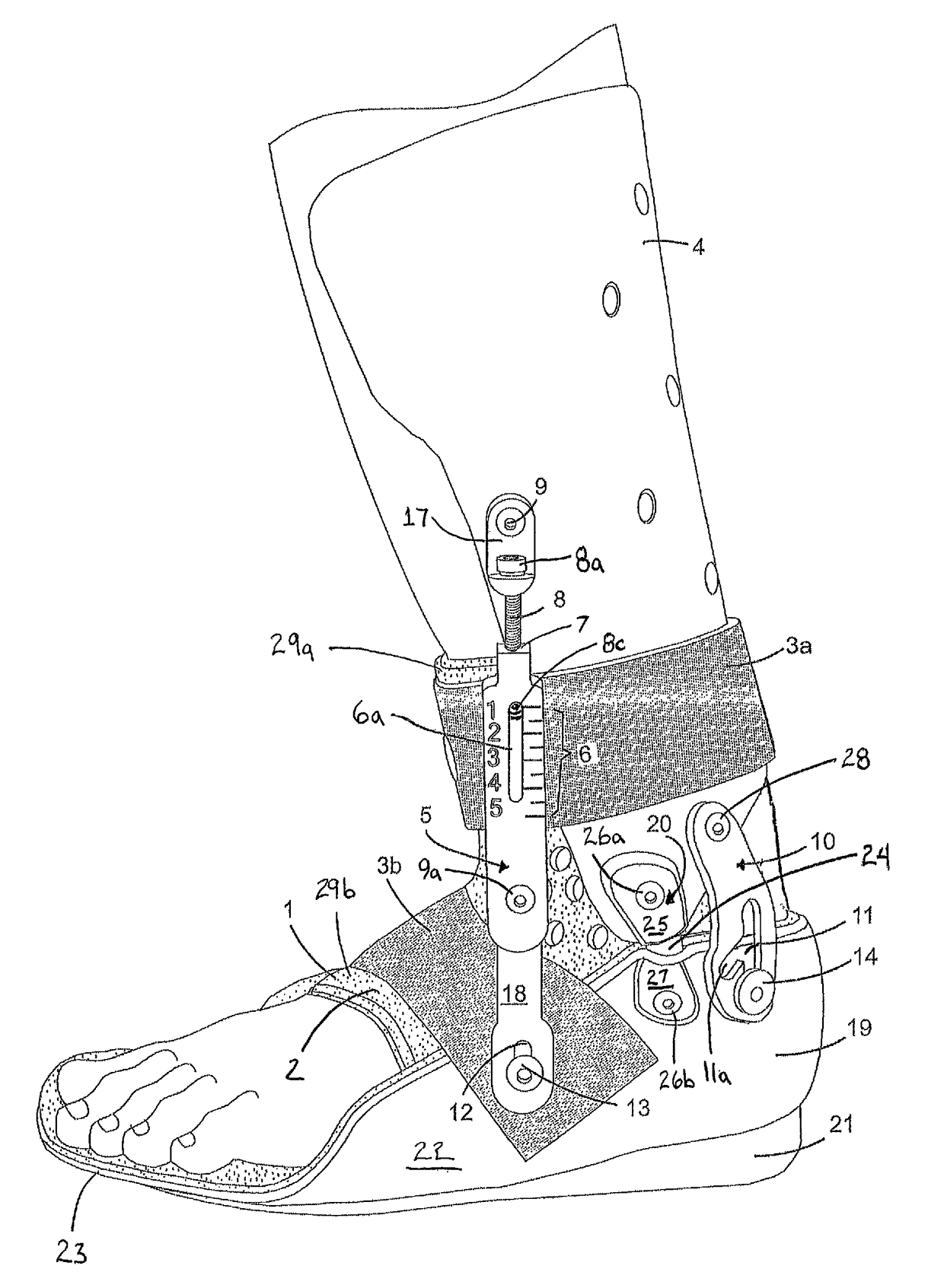
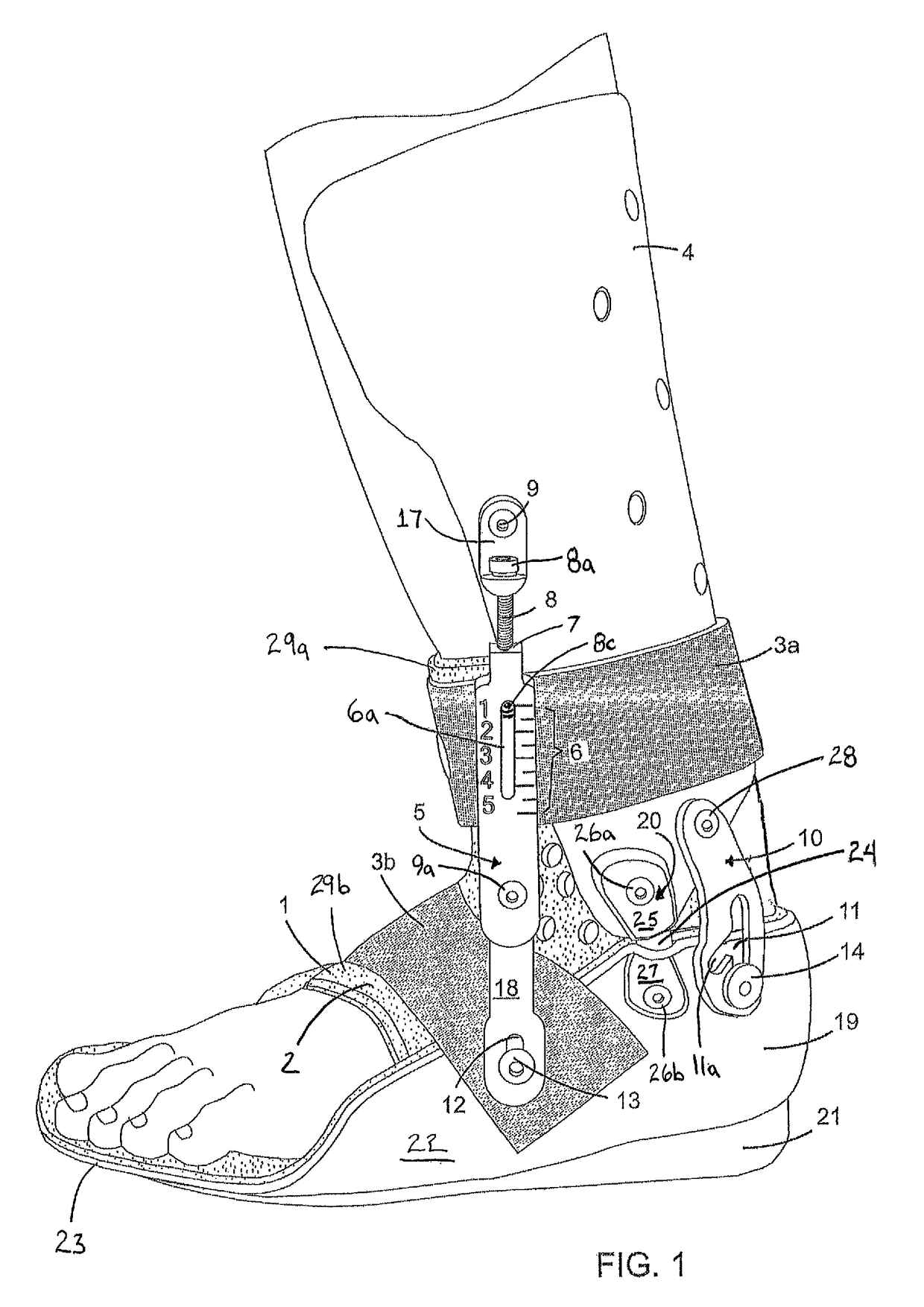
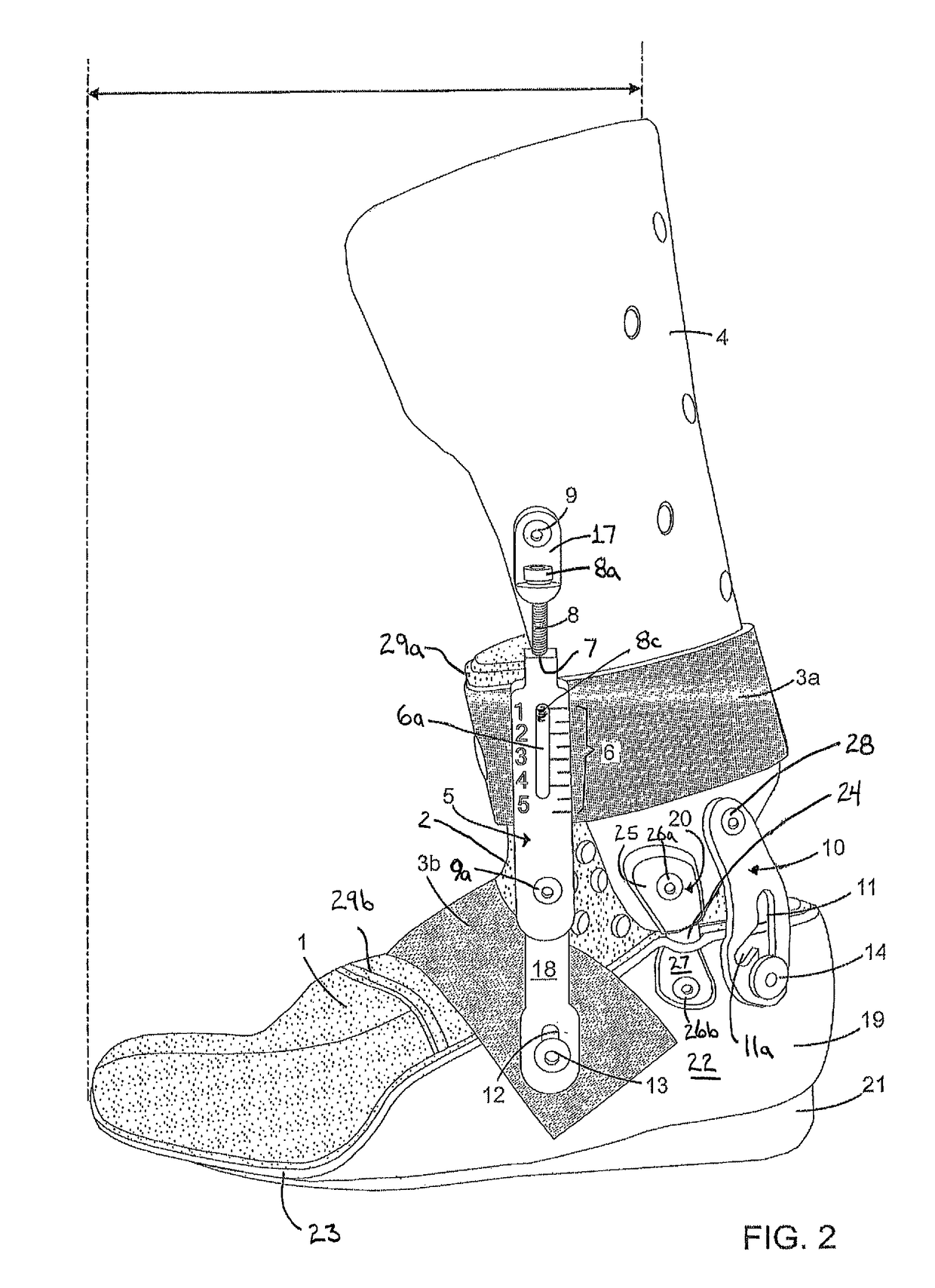
[0023]The present invention will now be described with reference to the accompanying figures, wherein the numbered elements in the following written description correspond to like-numbered elements in the figures. In the embodiment shown in FIGS. 1-4, the orthosis includes a molded inner boot or inner boot assembly 1, an upper or posterior shell 4, and a lower or foot shell 19, with shell 4 and shell 19 being rigidly formed of molded plastic and a sole 21 affixed to the bottom of foot shell 19. Also included are a static strap 3b and a stretchable elastic strap 3a used to secure a patient's foot and ankle within the orthosis, such as by hook and loop fastener connections to shell 19 and shell 4, respectively, in the illustrated embodiment. As shown in FIGS. 1-4 and 8, posterior shell 4 has a generally semi-cylindrical shape that conforms to the posterior lower calf and upper ankle region of a patient, with foot shell 19 including a wall portion 22 defining a heel receiving cavity an...


PUM


Abstract

An ankle foot orthosis that may be used for children with lower extremity spasticity or muscle weakness to prevent deformity and enhance extremity function. The orthosis includes an adjustable tension assembly connected to an upper leg portion and a lower foot portion. The tension assembly includes a tension adjuster connected with an elastomer band, with the tension adjuster being operable to selectively increase or decrease the amount of stretch applied to the elastomer band to provide a selectable upward biasing force to a patient's foot. The dynamic orthosis creates a variable load stretch below the knee preventing muscle contracture, heel cord shortening, and increases range of motion and is utilized during rest, sleep, and short distant weight bearing providing readings of the range of motion continuously. The orthosis incorporates a circumferential dynamic support system that maintains corrected alignment of the bones of the foot and ankle.

Description

CROSS REFERENCE TO RELATED APPLICATION[0001]The present application is a continuation-in-part of U.S. nonprovisional patent application Ser. No. 12 / 658,427, filed Feb. 5, 2010, by Grant C. Meyer and Daniel R. Ware, which is hereby incorporated herein by reference.BACKGROUND OF THE INVENTION[0002]The present orthosis invention relates to an, ankle foot orthosis designed for increasing the range of motion and correcting the alignment of a patient's foot and ankle.[0003]Children having spasticity, a condition often scene in cerebral palsy and similar types of medical disorders, are generally confronted with muscle imbalance, as their muscles do not work together in the manner of non-spastic children. The spasticity makes their muscles overpower other muscles creating unwanted pulls or forces on their joints. This imbalance of muscle pulls and involuntary forces, usually called spastic contractures, creates misalignment of involved joints. If this misalignment is not corrected and range...

Claims


Application Information

Patent Timeline
Patent Type & Authority Patents(United States)
IPC IPC(8): A61F5/00A61F5/01
CPCA61F5/0127
Inventor MEYER, GRANT C.WARE, DANIEL R.
Owner MEYER GRANT C
Why Eureka
Eureka Blog
Learn More