Microstructured composite particles

a composite particle and microstructure technology, applied in the field of microstructured composite particles, can solve the problems of porous resin particle structure, high cost and inconvenience, etc., and achieve the effect of reducing the cost of the end produ

Active Publication Date: 2017-07-18
SCHAEFER KALK
View PDF20 Cites 2 Cited by
  • Summary
  • Abstract
  • Description
  • Claims
  • Application Information

AI Technical Summary

Benefits of technology

[0059]First, adding the composite particles of the present invention as an additive to thermoplastically processable polymers, in particular to thermoplastic polymers, preferably to polyamides and to resorbable polymers, preferably to resorbable polyesters, especially to poly-D-, poly-L- and / or poly-D,L-lactic acid, improves the properties thereof, in particular their mechanical properties and also their suitability for biomedical applications, in a specific manner.
[0225]For this use in particular, the composite particles of the present invention advantageously have a structure whereby a fluidic substance, preferably the blowing agent, can penetrate into the polymer and preferably can effect at least partial solution of said polymer. In the case of composite particles having a core comprising at least one preferably thermoplastic polymer and a sheath comprising at least one calcium salt, preferably at least one calcium carbonate, especially at least one precipitated calcium carbonate, the sheath is at least partly permeable for the fluidic substance, especially for the blowing agent. This is preferably achieved by not less than 0.1%, preferably not less than 0.5% and especially from 1.0% to 5% of the core surface not being coated with calcium salt, preferably not with calcium carbonate and especially not with precipitated calcium carbonate. This effect is preferably amplified by the gaps between individual calcium salt particles, preferably between the individual calcium carbonate particles, especially between the individual precipitated calcium carbonate particles, which preferably are present and lead to the formation of appropriate microchannels for the fluidic substance, especially for the blowing agent.

Problems solved by technology

The procedure of the U.S. Pat. No. 6,403,219 B1 patent is therefore associated with appreciable cost and inconvenience.
This specific, extremely costly and inconvenient procedure of this printed publication leads to a porous structure on the part of the resin particles.
One disadvantage of conventional polylactide implant materials is that they are invisible in an x-radiograph.
Measurement of treatment progress by x-raying is accordingly impossible.

Method used


Image

  • Microstructured composite particles
  • Microstructured composite particles
  • Microstructured composite particles

Examples


example 1

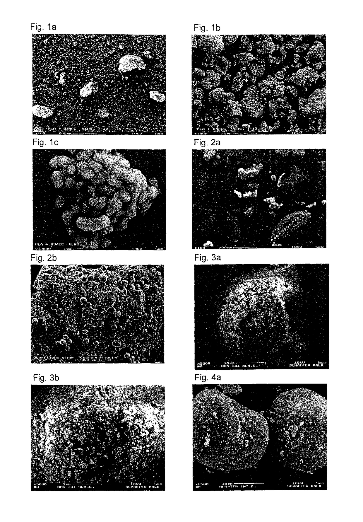
[0236]Microstructured composite particles comprising amorphous calcium carbonate and an amorphous polylactide (PLA) were prepared in accordance with the method described in JP 62083029 A by using the NHS 0 apparatus. Cold water at 12° C. was used for cooling. A polylactide pellet material (average particle size 3 mm) was used as mother particles and amorphous calcium carbonate powder (DSACC; average particle size 1 μm) was used as the baby particles.

[0237]16 g of polylactide pellet material were mixed with 4 g of CaCO3 powder and filled at 5000 rpm. The rotor speed of the assembly was adjusted to 16 000 rpm (100 m / s) and the added materials were processed for 1 min. This procedure was repeated with the same quantities of materials and the same machine settings. Altogether 38 g of structured composite particles were obtained.

[0238]SEM analysis showed that the PLA surface is substantially covered with the sphere-shaped DSACC particles (see FIG. 1a, 1b, 1c).

example 2

[0239]Microstructured composite particles comprising calcium carbonate spheres (spherulites; SPH) and an amorphous polylactide (PLA) were prepared as described in Example 1 using NHS 0. The same polylactide pellet material as described in Example 1 was used as mother particles, while calcium carbonate spheres (spherulites) having an average particle diameter of 7 μm were used as the baby particles.

[0240]16 g of polylactide pellet material were mixed with 4 g of CaCO3 powder and filled at 5000 rpm. The rotor speed of the assembly was adjusted to 16 000 rpm (100 m / s) and the added materials were processed for 1 min. Altogether 5 repeats were carried out with the same quantities of materials and the same machine settings. Altogether 85 g of structured composite particles were obtained.

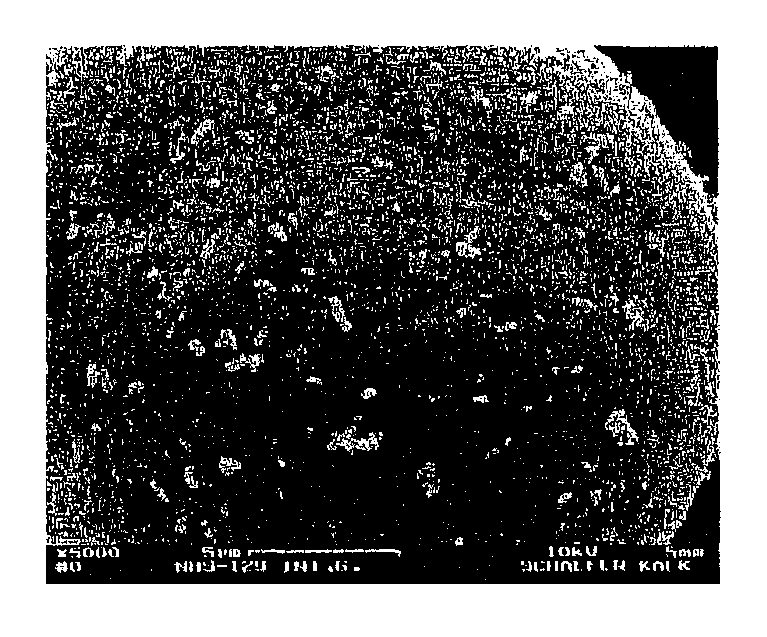
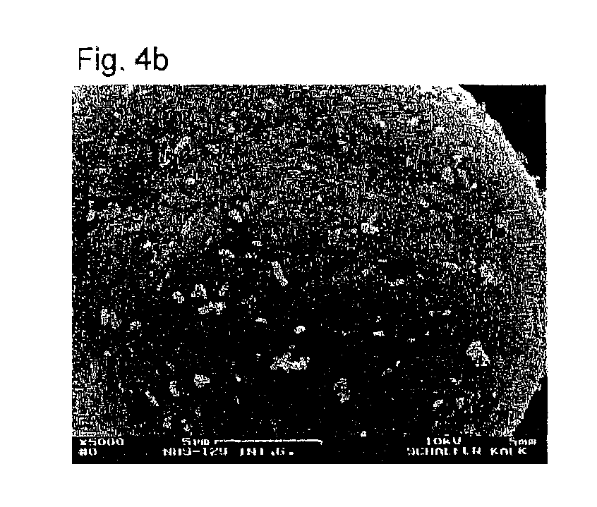
[0241]The SEM analysis of the structured composite particles obtained is depicted on the following SEM pictures. The PLA surface is only partly covered with the calcium carbonate spheres (spherulites) (se...

example 3

[0242]Microstructured composite particles comprising a calcium carbonate of mixed particulate shape (scalenohedra and needles; Schaefer Precarb® 400) and a fine powder based on polyamide-12 (PA12) were prepared using NHS 1. Cold water at 12° C. was used for cooling. PA12 (average particle size 50 μm) was used as mother particles, while Schaefer Precarb® 400 calcium carbonate (average particle size 0.7 μm) was used as the baby particles.

[0243]85 g of PA12 powder were mixed with 15 g of Schaefer Precarb® 400 CaCO3 powder and filled at an assembly rotor speed of 4000 rpm (50 m / s). The added materials were processed for 1 min. Altogether 8 repeats were carried out with the same amounts of materials and the same machine settings. Altogether about 760 g of structured composite particles were obtained.

[0244]The SEM analysis of the structured composite particles obtained is depicted in FIG. 3a, 3b.

[0245]The CaCO3 content determined using thermogravimetric analysis was 14.4% of PCC.

[0246]Th...


PUM

PropertyMeasurementUnit
particle diameteraaaaaaaaaa
particle sizeaaaaaaaaaa
thicknessaaaaaaaaaa

Abstract

Microstructured composite particles obtainable by a process in which large particles are bonded to small particles. The composite particles are preferably used as an additive, especially as a polymer additive, as an additive or starting material for the production of components, for applications in medical technology and / or in microtechnology and / or for the production of foamed articles.

Description

TECHNICAL FIELD[0001]The present invention concerns microstructured composite particles, their methods of making and their use.BACKGROUND ART[0002]Composites are already known, a composite being an engineering material consisting of two or more combined materials which possesses properties as an engineering material not possessed by its individual components. Yet component properties as materials and component geometry do play a part in determining the properties of the composites. Size effects often play a particular part. The bond between the combined components is generally chemical or mechanical or a combination thereof.[0003]Microstructured composite particles are also already known per se.[0004]For example, European patent application EP 0 523 372 A1, by citing Japanese patent application JP62083029 A, discloses a process wherein a first material (referred to as “mother particles”) is surface coated with a second material which consists of smaller particles (referred to as “ba...

Claims


Application Information

Patent Timeline
Patent Type & Authority Patents(United States)
IPC IPC(8): B32B5/16B01J2/00C08J3/12C09C1/00C09C1/02B33Y70/00
CPCB32B5/16B01J2/006C08J3/128C09C1/0081C09C1/02C09C1/021C09C1/025B33Y70/00C01P2002/02C01P2004/01C01P2004/03C01P2004/10C01P2004/20C01P2004/32C01P2004/54C01P2004/62C01P2004/80C08J2367/04Y10T428/2991A61L27/40B01J2/003C08J3/20C08L67/04
Inventor VUCAK, MARIJANNOVER, CHRISTOPH
Owner SCHAEFER KALK
Why Eureka
Try Eureka