Operating member with switching mat

a technology of operating member and switching mat, which is applied in the field of operating member, can solve the problems of affecting the switching function, the geometrical design of the contact pill is limited by the dimensions of the respective cavity, and the contact pill is subject to mechanical wear, so as to increase the reliability of the switching function.

Active Publication Date: 2017-07-18
PREH GMBH
View PDF5 Cites 1 Cited by
  • Summary
  • Abstract
  • Description
  • Claims
  • Application Information

AI Technical Summary

Benefits of technology

[0011]While the tactile feel is adaptable over a wide range via the shape of the dome, its wall thickness and the material properties of the basic material, the electrical properties of the key can now be determined independently of the tactile feel via the size of the contact pill and its material properties. For example, the contact pill is made from a carbon-containing material or provided by means of a coating, or it may be a so-called supraconductive pill (SC pill), i.e. a silicone-filled nickel lattice. According to the invention, the contact pill may be a gold plate or a gold foil or a metallic snap plate. The design that is independent of the tactile feel of the contact pill, such as the thickness and size of the contact surface, permits the realization of an electrical function of the operating member that is as space-saving, stable in the long term and reliable, even at high temperature fluctuations, as possible. Preferably, the switching mat including the tactile-feel dome and the contact pill is configured integrally; for example, a substance-to-substance connection is provided between the contact pill and the rest of the switching mat.
[0015]According to a preferred embodiment of the operating member, the open contacting portion is disposed on a component-carrying side of the circuit board. The component-carrying side means a side of the board that is equipped with parts. Due to the separation of the tactile-feel dome and the switching dome according to the invention, open contacting portions can be integrated into the component-carrying side of a board. In known solutions, an otherwise unequipped circuit board or at least the component-free area of a circuit board is usually used for the arrangement of an open contacting portion and for supporting the switching mat. This is no longer necessary due to the principle according to the invention. The solution according to the invention provides the possibility of disposing the open contacting portion on the equipped side of the circuit board and to surround it with electronic components at a small clear distance of less than 5 millimeters, preferably less than 2 millimeters, still more preferably less than 1 millimeter, in order thus to advantageously save construction space.
[0021]Preferably, the contact pill is disposed on the side of the switching mat facing away from the unilaterally open hollow volume defined by the tactile-feel dome. As a rule, the tactile-feel dome has a shape that tapers to a point in an opposite direction to the actuation direction; for example, it has a frustoconical configuration. This means that the tactile-feel dome, as a rule, requires more construction volume and more support surface at the end thereof forming the hollow volume, compared with its opposite, “pointed” end. Because more construction space is thus available for the contact pill due to the smaller spatial extension at the pointed end, its contact surface can be dimensioned more generously, which increases the reliability of the switching function.

Problems solved by technology

Though it is possible to determine the electrical properties of the operating member through the selection of the contact pill, however, due to the fact that the contact pill is disposed in the cavity defined by the associated tactile-feel dome, its geometrical design, however, is limited as regards its thickness and size by the dimensions of the respective cavity.
In addition, the contact pill is subject to mechanical wear which, as a rule, affects the switching function.
Due to the limitation of the cavity as regards space, this cannot be counteracted by a corresponding design of the contact pill, for example.

Method used


Image

  • Operating member with switching mat
  • Operating member with switching mat

Examples


Embodiment Construction

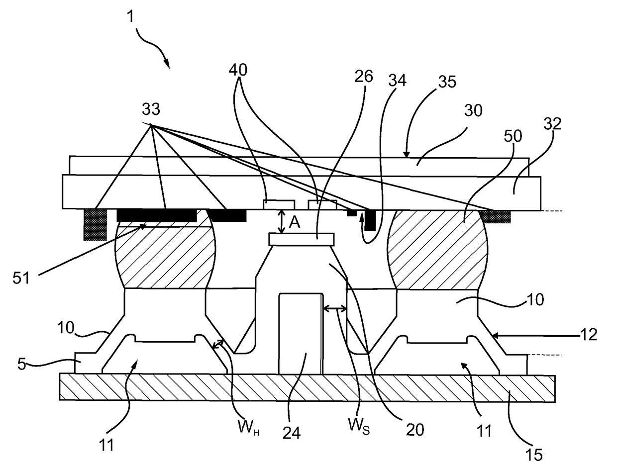
[0026]FIG. 1 shows a cross section of an operating member 1 according to the invention. It comprises a switching mat 5 made of elastic silicone rubber and an operating member 30 disposed above it in its rest position. The actuating part 30 defines a touch-sensitive input surface 35. For example, the actuating part 30 comprises a touchpad or touchscreen, which carry out a spatially resolving detection of the touch by means of a resistive or capacitive measurement. The actuating part thus defines a touch-sensitive input surface 35. A circuit board 32 is disposed as a flat structure underneath the flat actuating part 30 and adjacent and rigidly connected thereto. The circuit board 32 is equipped on one side, so that the side equipped with electronic components 33 is disposed facing away from the actuating part. For example, the components 33 are provided for carrying out the evaluation in respect of the spatially resolving detection of the touchpad of the touchscreen. The actuating par...


PUM


Abstract

An operating member including an actuating part movably mounted between a rest position and a switching position, a circuit board with an open contacting portion, a switching mat made of an elastic material disposed adjacent to the circuit board, and at least one contact pill formed on a side of the switching mat facing towards the circuit board, which cooperate in such a way that, in the switching position of the actuating part at the latest, the open contacting portion of the circuit board is closed by the contact pill, and where the switching mat moreover forms at least one tactile-feel dome which is associated with the contact pill, is elastically compressible by actuation of the actuating part in the direction of the switching position and which, in its initial position, defines a unilaterally open hollow volume in the switching mat, in order to cause a tactile feedback on the actuating part, where the contact pill is disposed outside the hollow volume defined by the tactile-feel dome.

Description

CROSS REFERENCE TO RELATED APPLICATION[0001]This application is related to and claims the benefit of German Patent Application Number 10 2014 114 170.9 filed on 30 Sep. 2014, the contents of which are herein incorporated by reference in their entirety.TECHNICAL FIELD[0002]The present invention relates to an operating member with an electrical switching functionality realized by means of a switching mat, in particular for the automobile sector.BACKGROUND[0003]Such a switching mat, also referred to as switching mat or keyboard mat, is the central component in many operating members, particularly those with a key switching functionality. It determines the feel, i.e. the tactile impression, but also the electrical behavior via the integrated contact pill. Such switching mats, which are disposed above a circuit board, also referred to as printed circuit board, are usually made from silicone rubber and, due to the combination of tactile feel or return action and electrical switching funct...

Claims


Application Information

Patent Timeline
Patent Type & Authority Patents(United States)
IPC IPC(8): H01H13/702H01H13/14H01H13/88G06F3/044
CPCH01H13/14G06F3/044H01H13/702H01H13/88H01H2215/00G06F3/0338G06F3/03547H01H13/26H01H13/52H01H25/041H01H2003/0293H01H2215/006H01H2215/008H01H2239/074
Inventor SAUER, MARCSTANGER, JUERGEN
Owner PREH GMBH
Why Eureka
Try Eureka