
USB power port control

a power port control and usb technology, applied in the direction of power supply for data processing, liquid/fluent solid measurement, instruments, etc., can solve the problems of stressing these components, increasing the current limit that must be supported by usb power port switches, and increasing the current limi

Active Publication Date: 2017-07-25
MICROCHIP TECH INC
View PDF20 Cites 15 Cited by
  • Summary
  • Abstract
  • Description
  • Claims
  • Application Information

AI Technical Summary

Benefits of technology

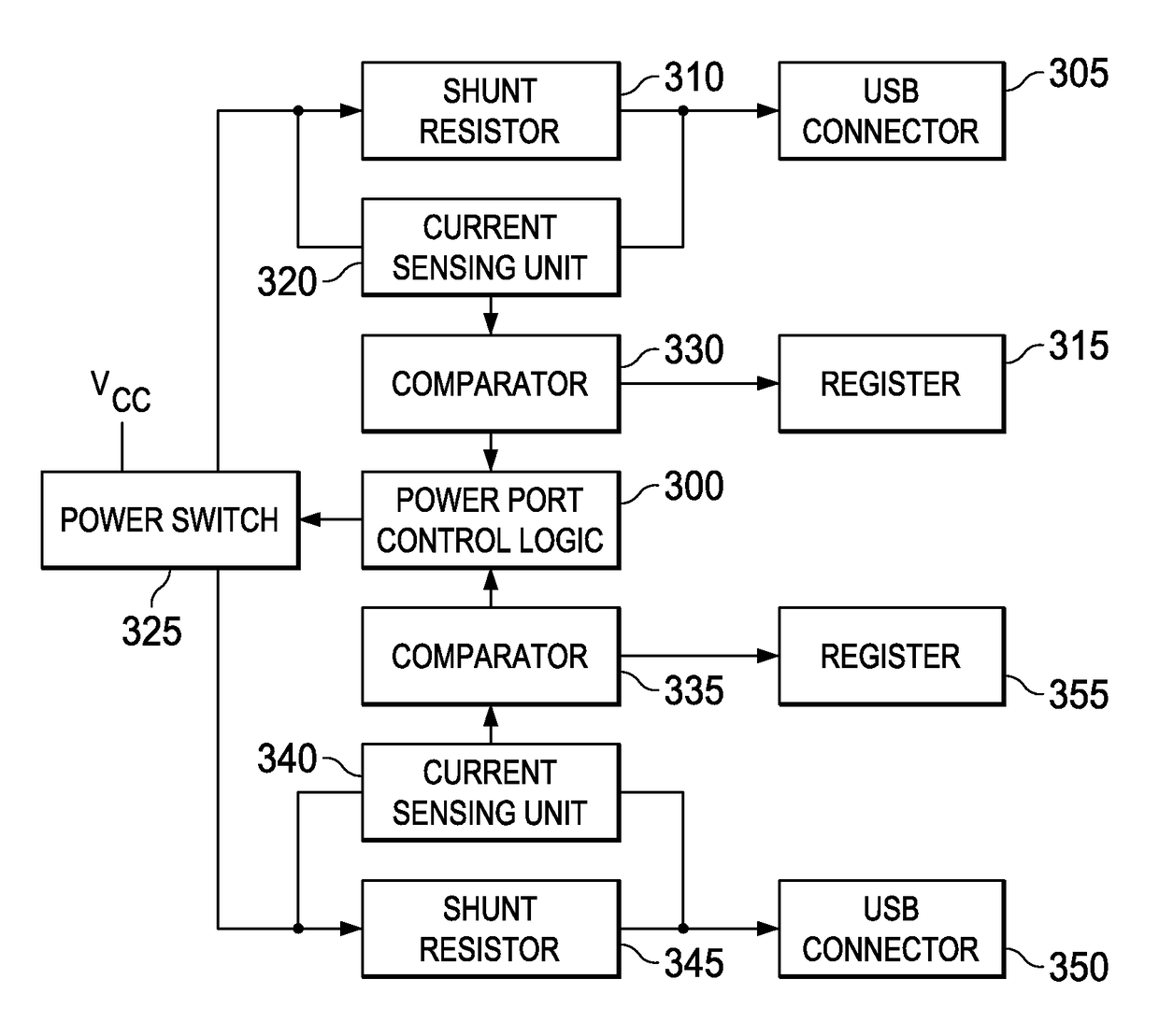
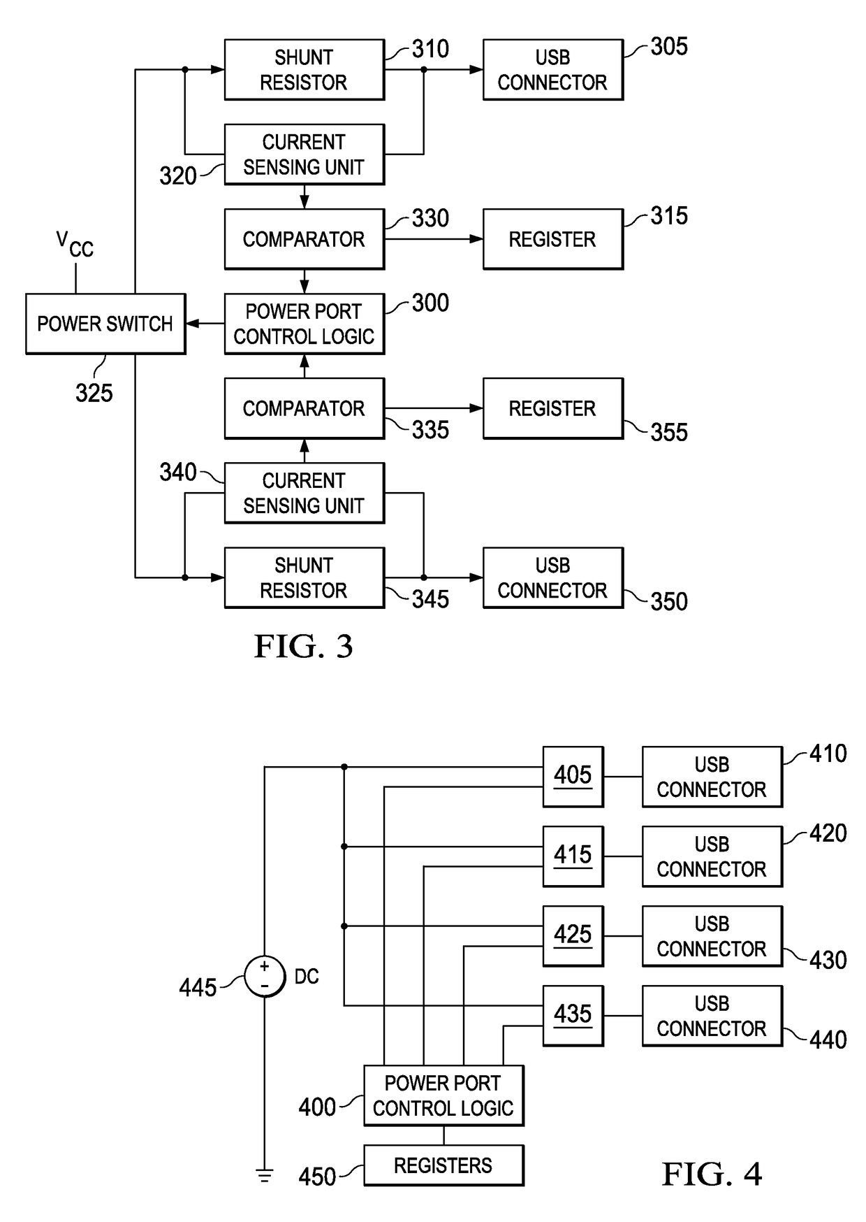
This patent describes a power switch that can provide the benefits of both individual mode and ganged mode power switching. The switch includes multiple USB ports, a power element, current measurement units, and a logic unit. The current measurement units measure the current drawn by a group of USB ports, and the logic unit controls the power element. If the current measurements exceed a limit set for the group, the logic unit directs the power element to turn off the supply of current to all USB ports. The power element can be a power switch or a controllable power supply. The current measurement units include a shunt resistor and a current sensing unit, and a register stores a current limit for each USB port sub-group. The logic unit can retrieve and compare the current measurements to the stored current limits, and it can also use an analog-to-digital converter. The technical effect is a power switch with the ability to provide the benefits of both individual and ganged mode power switching.

Problems solved by technology

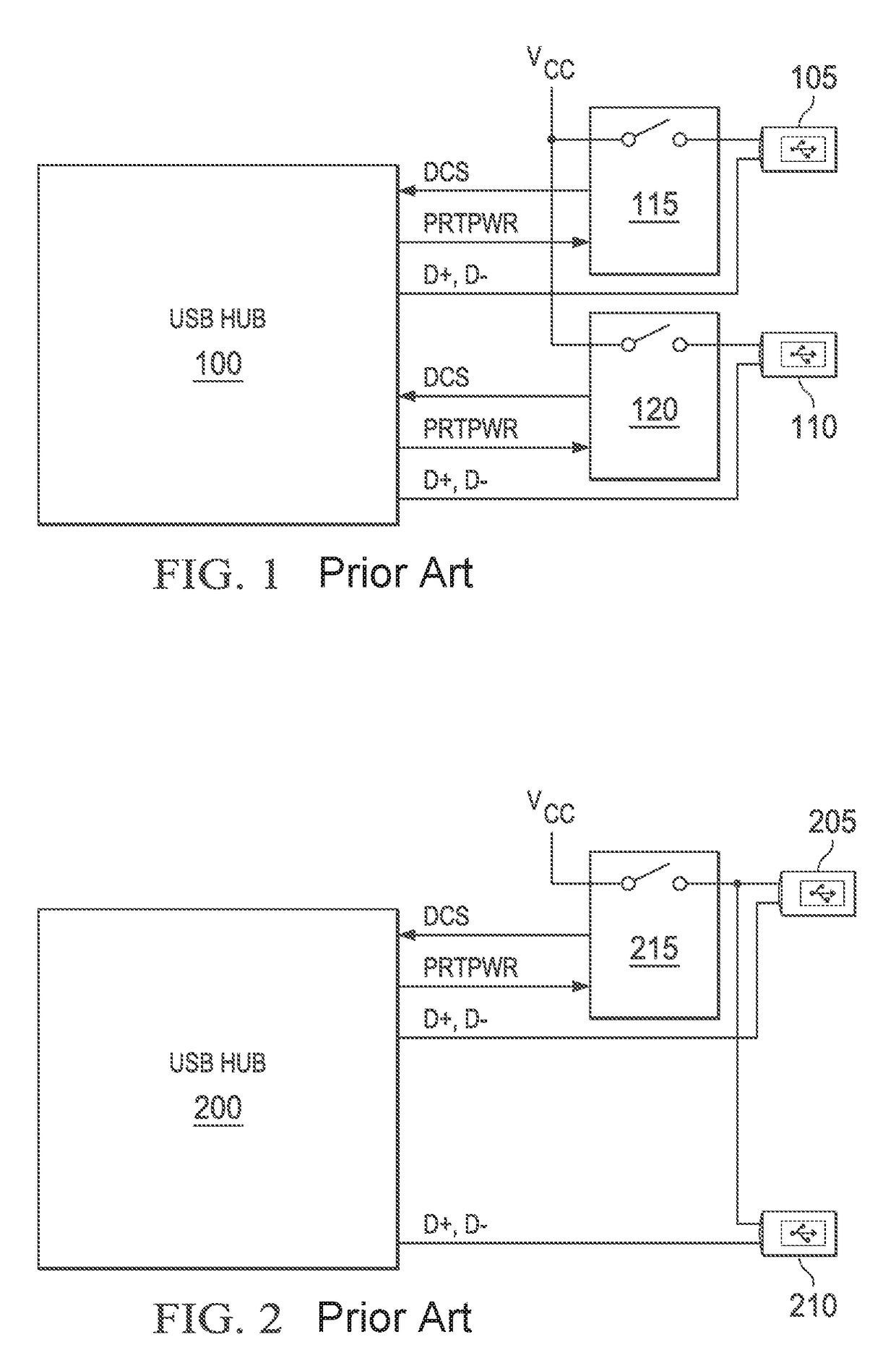
Despite the cost savings provided by gang mode power switching, as USB charging ports become more prevalent and the current limits being supported by USB ports increase, gang mode power switches place greater demands on the USB connectors used to deliver this power.
Moreover, the current limits that must be supported by USB power port switches have gradually increased as the current draws supported by USB have been increased.
As a result, USB connector components used in gang mode power switches may be exposed to current levels that exceed the current ratings for the USB connectors, thus stressing these components and increasing malfunctions and failures.

Method used


Image

  • USB power port control
  • USB power port control
  • USB power port control

Examples


Embodiment Construction

[0021]The disclosure and various features and advantageous details thereof are explained more fully with reference to the exemplary, and therefore non-limiting, embodiments illustrated in the accompanying drawings and detailed in the following description. Descriptions of known programming techniques, computer software, hardware, operating platforms and protocols may be omitted so as not to unnecessarily obscure the disclosure in detail. It should be understood, however, that the detailed description and the specific examples, while indicating the preferred embodiments, are given by way of illustration only and not by way of limitation. Various substitutions, modifications, additions and / or rearrangements within the spirit and / or scope of the underlying inventive concept will become apparent to those skilled in the art from this disclosure.

[0022]Additionally, any examples or illustrations given herein are not to be regarded in any way as restrictions on, limits to, or express defini...


PUM


Abstract

A system, method and device for providing over-current protection to USB ports comprised in a USB hub, whereby a single switch is used to control the power supply to one or more groups of USB ports based on determinations whether the current drawn by a group of USB ports has exceeded a predefined current limit. Embodiments provide the cost savings associated with gang mode power port switching and the reduced stress on USB components and individualized protection of USB ports associated with individual mode power switching. Embodiments utilize a plurality of current measurement units to measure the current drawn by each group of USB ports supported by a switch and further utilize a power port control logic unit to control the switch based on whether the current measurements have exceeded a current limit.

Description

CROSS-REFERENCE TO RELATED APPLICATIONS[0001]This application claims the benefit of U.S. Provisional Application No. 61 / 989,112 filed on May 6, 2014, which is incorporated herein in its entirety.TECHNICAL FIELD[0002]The present disclosure relates to universal serial bus (USB) technology, in particular power switches for providing over-current protection on USB ports comprised in a USB hub.BACKGROUND OF THE INVENTION[0003]The Universal Serial Bus (USB) standard was developed to provide personal computer users with a single hardware and software interface for connecting a wide range of peripherals to desktop and laptop computers. USB has become the interface of choice for peripheral devices because it offers simple connectivity and a standardized interface that has proven effective for communicating with a vast array of peripheral devices. In addition to providing a standardized interface for communications between a peripheral device and a host device, USB provides the ability to tra...

Claims


Application Information

Patent Timeline
Patent Type & Authority Patents(United States)
IPC IPC(8): G06F1/32G06F1/26G06F1/28
CPCG06F1/3287G06F1/266G06F1/28G06F1/3253G06F2200/261Y02D10/00
Inventor KAESTNER, CLEMENS
Owner MICROCHIP TECH INC
Learn More