
Method and apparatus for facilitating delivery of anaesthetic

a technology of anaesthesia and delivery method, which is applied in the field of facilitating anaesthesia, can solve the problems of poor dynamic response to changes in patient demand for increased anaesthesia concentration, unsatisfactory for all types of patients, and patient may not be put back to sleep in appropriate tim

Active Publication Date: 2017-08-01
DUNLOP COLIN
View PDF17 Cites 1 Cited by
  • Summary
  • Abstract
  • Description
  • Claims
  • Application Information

AI Technical Summary

Benefits of technology

The apparatus improves the dynamic response of anaesthetic circuits, allowing for more efficient use with smaller patients, reducing anaesthetic gas flow and waste, and maintaining precise anaesthetic concentration, while being cost-effective and environmentally friendly.

Problems solved by technology

There are a number of issues with Re-Breather circuits and they are not necessarily ideal for all types of patients.
One problem associated with Re-Breather circuits is a poor dynamic response to changes in patient demand for increased anaesthetic concentration.
Poor dynamic response (depending, in part, on patient type) can mean that the patient may not be put back to sleep in appropriate time, or receive the right amount of anaesthetic to keep them at the correct anaesthetic depth.
Re-Breather circuits also have a certain amount of resistance to breathing, which may not be suitable for all types of patients.
Although currently available Re-Breather circuits may perform satisfactorily to maintain anaesthetic depth of adult sized human patients e.g. 40 kg and over, there are issues with their use by smaller patients, particularly under 15 kgs.
Because of the difficulties with smaller patients, such, as small animals, and the impracticality of designing Re-Breather circuits particularly for smaller patients, typically small patients such as small animals are not anaesthetised using Re-Breather circuits.
This is very expensive.
Also, a significant amount of anaesthetic leaks into the surrounding environment from the open system, causing a potential health hazard.
The active provision and removal of anaesthetic / gas mixture is therefore very wasteful and expensive.
With open systems, it is also very difficult to ensure with any precision that a patient is anaesthetised.
It is difficult to tell with any accuracy the concentration of anaesthetic gas mixture at the patient respiratory orifices.
It can therefore be very difficult to maintain anaesthetic depth with open circuits.

Method used


Image

  • Method and apparatus for facilitating delivery of anaesthetic
  • Method and apparatus for facilitating delivery of anaesthetic
  • Method and apparatus for facilitating delivery of anaesthetic

Examples


Embodiment Construction

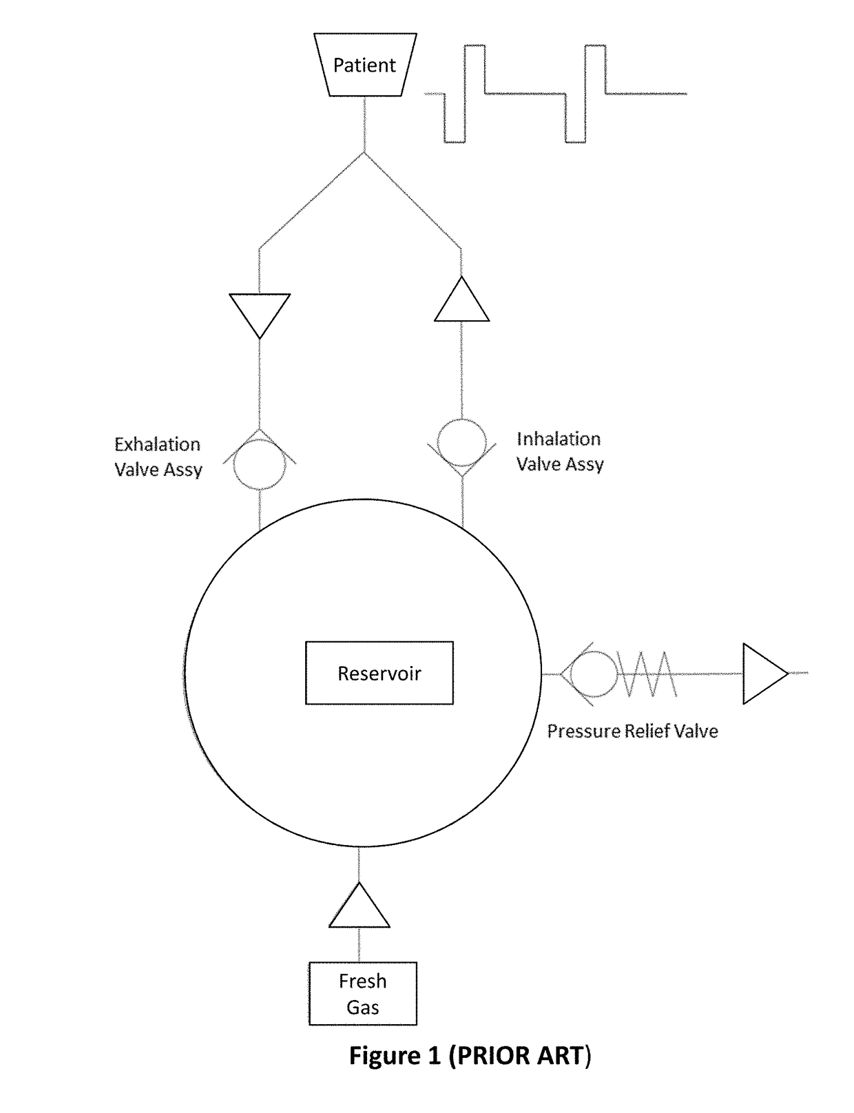
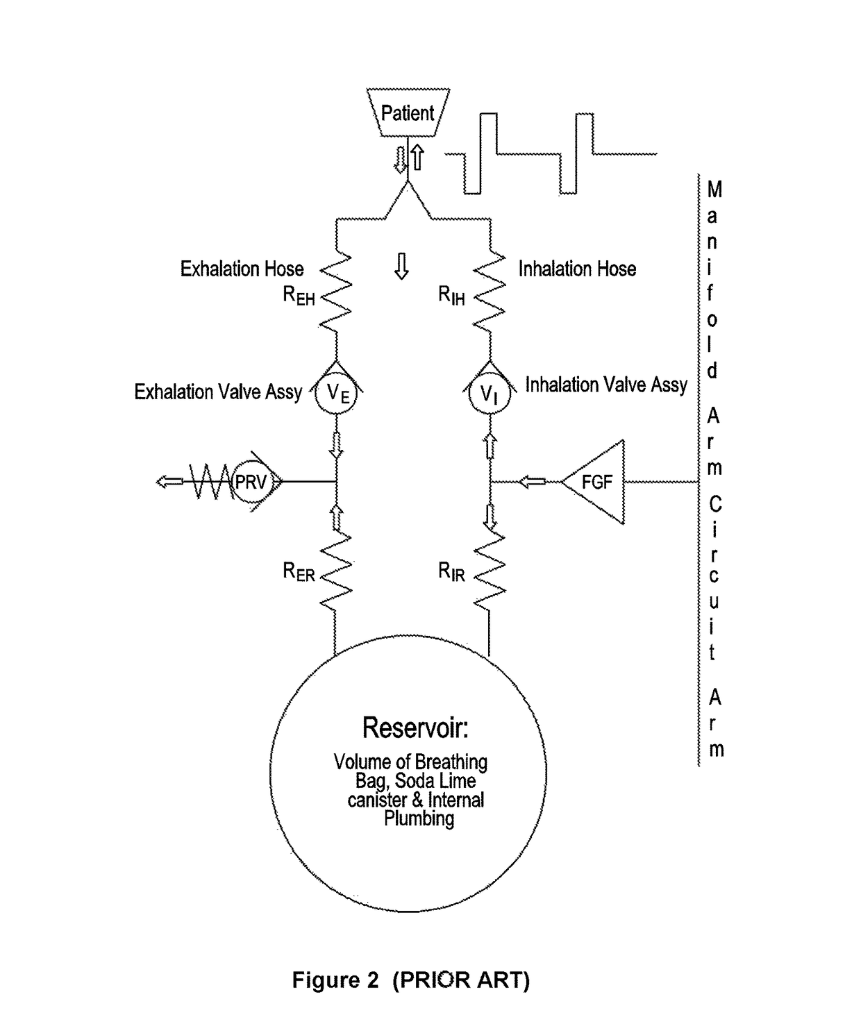
[0073]Referring to FIG. 17, a prior art Re-Breather circuit for delivering anaesthesia to a patient is illustrated. This circuit allows oxygen / air to be Re-Breathed after it has been scrubbed of carbon dioxide. The circuit includes a means of providing oxygen, in this case, a gas cylinder 120 containing oxygen. A regulator 103 is provided to regulate the pressure of the oxygen supply and a flow meter 104 provides an indication of the gas flow. A vaporiser 105 is provided for the introduction of anaesthetic (and perhaps other additional gases) to the gas flow. Anaesthesia lines 125 and 126 connect to a “Y” piece 127 which may connect to a mask (not shown) as an interface with the patient. Fresh Gas flow comes down inspiration line 125 from the vaporiser 105 and from the rest of the circuit. Direction of gas flow is shown by arrow 128.

[0074]Exhaled (exhaust) gas flow travels up the other arm, expiration arm 126 in the direction of arrow 129. Scrubber 130, which in this embodiment may ...


PUM


Abstract

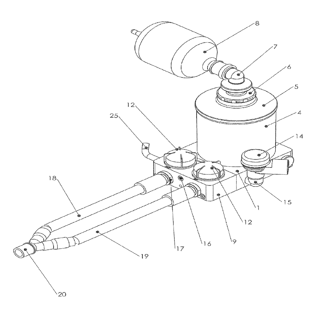
The present invention relates to a method and apparatus for facilitating anaesthesia, particularly in Re-Breather anaesthetic circuits. A problem with Re-Breather circuits is that their dynamic response can be relatively slow. The dynamic response is the response of the circuit to delivering changes of anaesthetic concentration. In current circuits, Fresh Gas containing anaesthetic is delivered into the circuit and may be substantially diluted by the gas already present in the circuit. It is therefore difficult to achieve a rapid increase of anaesthetic concentration for delivery to the patient. In the present invention, an accumulator is placed in the Re-Breather circuit to accumulate Fresh Gas containing anaesthetic as it is introduced into the circuit, adjacent an inhalation conduit to the patient. Fresh Gas containing high concentrations of anaesthetic is therefore immediately available to the patient.

Description

INCORPORATION BY REFERENCE TO RELATED APPLICATIONS[0001]Any and all priority claims identified in the Application Data Sheet, or any correction thereto, are hereby incorporated by reference under 37 CFR 1.57. This application is a continuation, under 35 U.S.C. §120, of International Patent Application No. PCT / AU2012 / 001428, filed on Nov. 19, 2012 under the Patent Cooperation Treaty (PCT), which was published by the International Bureau in English on May 23, 2013, which designates the United States, which claims benefit to priority of Australian Patent Application No. 2011904836 filed on Nov. 18, 2011, the disclosures of which are hereby expressly incorporated by reference in their entirety and are hereby expressly made a portion of this application.FIELD OF THE INVENTION[0002]The present invention relates to a method and apparatus for facilitating anaesthesia and, particularly, but not exclusively, relates to a method and apparatus of facilitating anaesthesia in a Re-Breather anaest...

Claims


Application Information

Patent Timeline
Patent Type & Authority Patents(United States)
IPC IPC(8): A61M16/12A61M16/22A61M16/20A61M16/10A61M16/01A61M16/08A61M16/18A61M16/00
CPCA61M16/127A61M16/0045A61M16/01A61M16/0891A61M16/104A61M16/1095A61M16/12A61M16/209A61M16/22A61M16/0051A61M16/0078A61M16/18A61M2016/0036A61M2202/0208A61M2202/0241A61M2202/0275A61M2205/3317A61M2205/3368A61M2230/432A61M16/0833A61M16/021
Inventor DUNLOP, COLIN
Owner DUNLOP COLIN
Learn More