
Canned-motor pump for vehicle

a technology for a vehicle and a canning motor, which is applied in the direction of machines/engines, liquid fuel engines, magnetic circuit shapes/forms/construction, etc., can solve the problems of increasing the air gap between the parts, vibration and noise, and not being desirable to consumers, so as to reduce the number of processes, reduce manufacturing costs, and minimize any air gap

Active Publication Date: 2017-08-01
HYUNDAI MOTOR CO LTD +1
View PDF46 Cites 0 Cited by
  • Summary
  • Abstract
  • Description
  • Claims
  • Application Information

AI Technical Summary

Benefits of technology

[0010]Accordingly, the present invention has been made keeping in mind the above problems occurring in the related art, and the present invention is intended to propose a canned motor pump in which an assembly gap is minimized to minimize an air gap therein, thereby enhancing performance and reducing noise.
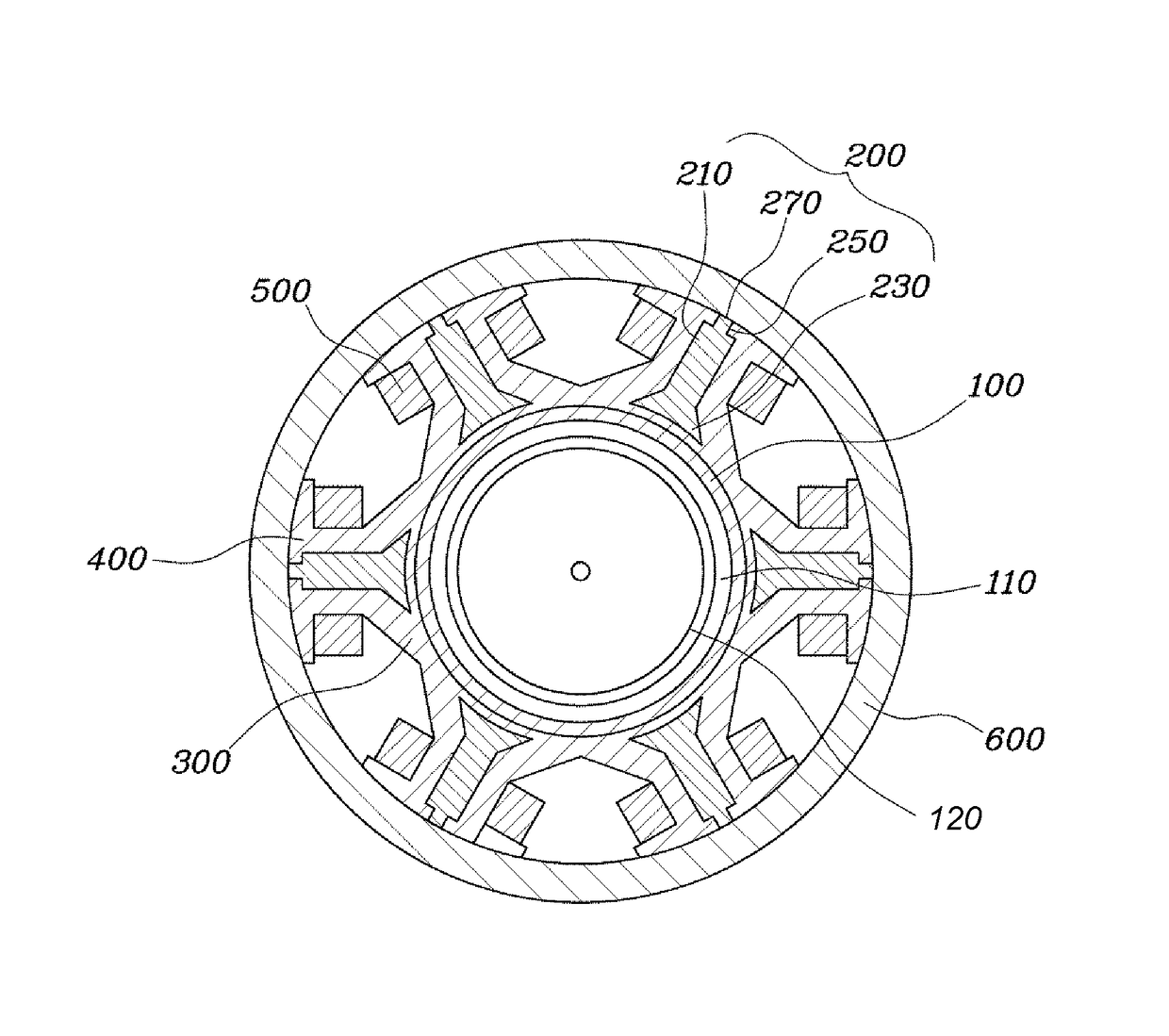
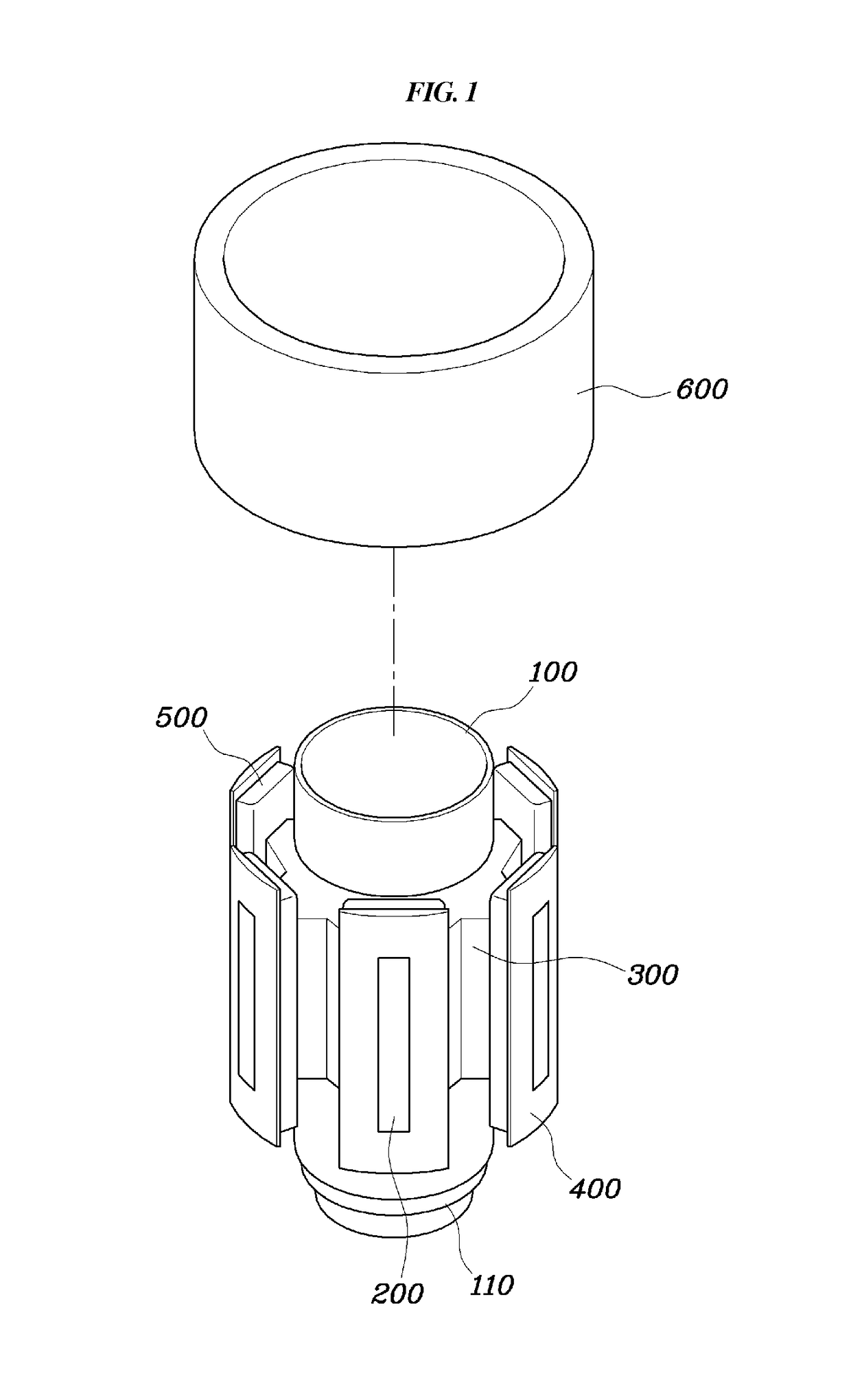
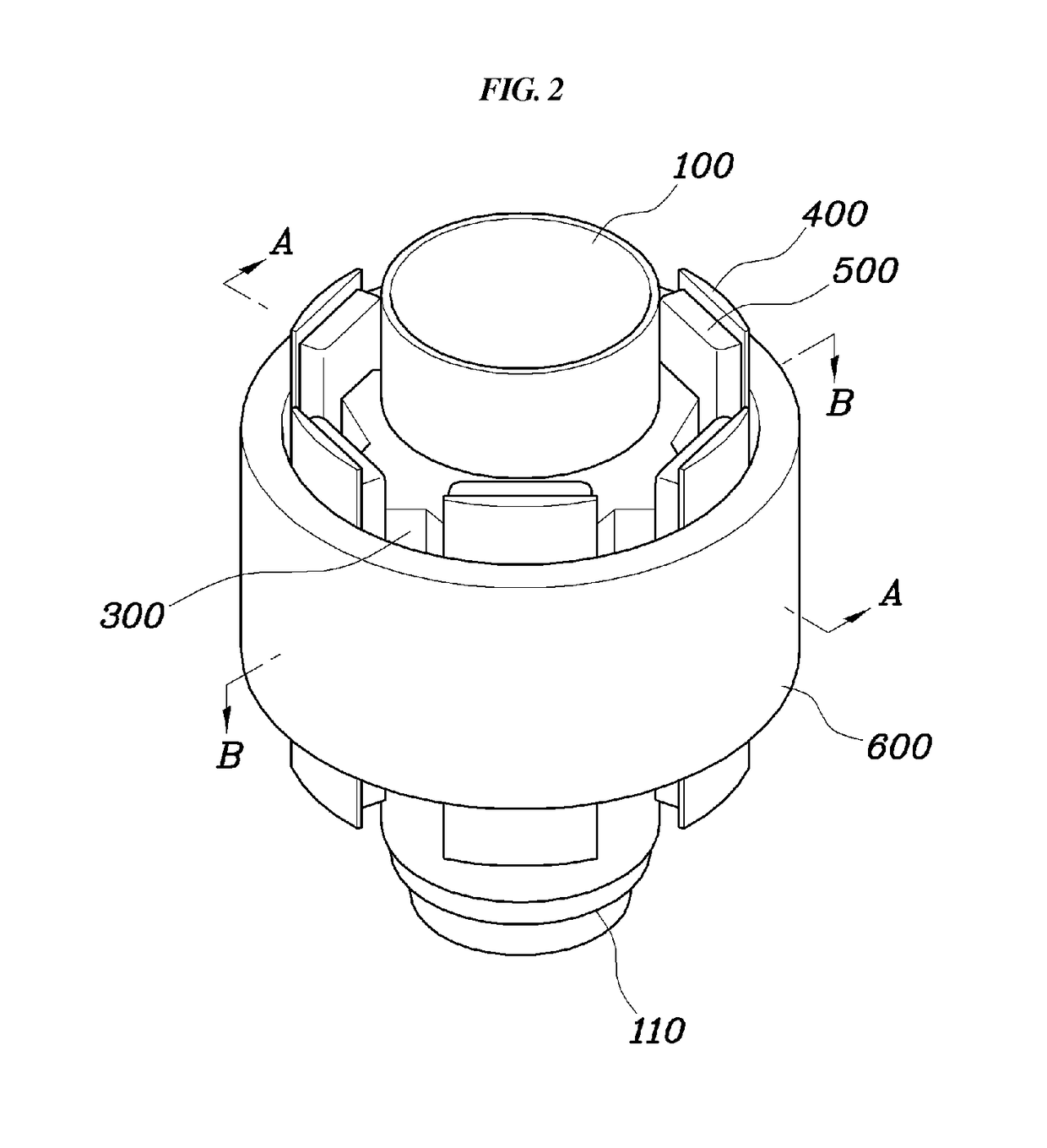
[0018]According to the canned motor pump having the above-described structure, the can structure can operate as an insulator and thus no separate insulator is required. It is also possible to reduce the number of processes and parts which are required for the assembly of the separate insulator, thereby reducing manufacturing cost. Additionally, since the outer ring and the divided cores are utilized, it becomes easy to concentrically wind the coils and it becomes possible to minimize any air gaps therebetween, thereby improving the performance characteristic of the motor. Since the number of parts that are required to manufacture a can part are reduce, the assembly gap is removed or minimized, thereby reducing noise. Finally, due to the unified structure, the pump does not create noise and has superior tolerance to vibration and impacts.

Problems solved by technology

However, when the can motors are made in the above manner, because the can is made separately and then is inserted into the state core, an assembly gap is created which increases an air gap therebetween.
The presence of such an air gap causes vibrations and noise, which are problematic (i.e., vibrations can cause parts to come loose and such noise is not desirable to consumers).

Method used


Image

  • Canned-motor pump for vehicle
  • Canned-motor pump for vehicle
  • Canned-motor pump for vehicle

Examples


Embodiment Construction

[0025]Hereinbelow, preferred embodiments of a canned motor pump according to the present invention will be described in detail with reference to the accompanying drawings.

[0026]The terminology used herein is for the purpose of describing particular embodiments only and is not intended to be limiting of the invention. As used herein, the singular forms “a”, “an” and “the” are intended to include the plural forms as well, unless the context clearly indicates otherwise. It will be further understood that the terms “comprises” and / or “comprising,” when used in this specification, specify the presence of stated features, integers, steps, operations, elements, and / or components, but do not preclude the presence or addition of one or more other features, integers, steps, operations, elements, components, and / or groups thereof. As used herein, the term “and / or” includes any and all combinations of one or more of the associated listed items.

[0027]It is understood that the term “vehicle” or “...


PUM

PropertyMeasurementUnit
outer circumferenceaaaaaaaaaa
inner circumferenceaaaaaaaaaa
lengthaaaaaaaaaa

Abstract

A canned motor pump that includes a pipe-shaped can part which accommodates a rotor, a plurality of supports protruding radially outward from sides of the can part, and a plurality of the split cores each of which is inserted inside a corresponding support of the supports. Each distal end of the split cores extends in a direction toward a corresponding insulator part. A plurality of insulator parts are respectively formed on distal ends of the supports. An annular outer ring surrounds the outer circumference of the insulator parts. The inner circumference of the outer ring adjoins to exposed outermost ends of the split cores. Coils then are wound on the supports to provide a can motor pump with fewer parts and better performance.

Description

CROSS REFERENCE TO RELATED APPLICATION[0001]The present application claims priority of Korean Patent Application Number 10-2013-0084513 filed on Jul. 18, 2013, the entire contents of which application are incorporated herein for all purposes by this reference.BACKGROUND OF THE INVENTION[0002]Field of the Invention[0003]The present invention relates to a canned motor pump for a vehicle in which a can structure is interposed between a rotor and a stator.[0004]Description of the Related Art[0005]Most modern day vehicles are provided with a water pump which circulates cooling water and an oil pump which circulates oil. In particular, water pumps, by way of example, the water pump can be divided into engine powered water pumps which operate by receiving power from an engine through a belt connected to an engine rotary shaft and electric water pumps which operate on electricity from a battery. Since the electric water pumps do not require power from the engine, they improve fuel efficienc...

Claims


Application Information

Patent Timeline
Patent Type & Authority Patents(United States)
IPC IPC(8): F04D13/06F04D29/02H02K1/14
CPCF04D13/0606F04D13/064F04D29/026H02K1/146F05D2230/20B29C45/1671F04D29/007F04D29/669F05D2210/11F05D2260/60Y10S415/00
Inventor KIM, HARK KOOLEE, SEUNG YONGKIM, CHI MYUNGPARK, JONG WONLEE, CHANG GOOK
Owner HYUNDAI MOTOR CO LTD
Learn More