Magnetic sensor, magnetic head, and biomagnetic sensor

a biomagnetic sensor and magnetic head technology, applied in the field of magnetic head, biomagnetic sensor, can solve the problems of noise caused by current applied between layers, low s/n ratio, and resistance of multi-layer films, and achieve high s/n ratio, high output, and high spatial resolution

Inactive Publication Date: 2017-08-01
TDK CORPARATION
View PDF30 Cites 2 Cited by
  • Summary
  • Abstract
  • Description
  • Claims
  • Application Information

AI Technical Summary

Benefits of technology

[0010]Since the areal resistance of the interface between the channel layer and the magnetization free layer is lower than the areal resistance of the interface between the channel layer and the magnetization-fixed layer, the resistance of the interface between the channel layer and the magnetization free layer is low as compared to the case where the areal resistance of the interface between the channel layer and the magnetization free layer is equal to the areal resistance of the interface between the channel layer and the magnetization-fixed layer; hence, detection noise can be reduced. Furthermore, the resistance of the interface between the channel layer and the magnetization-fixed layer is high as compared to the case where the areal resistance of the interface between the channel layer and the magnetization free layer is equal to the areal resistance of the interface between the channel layer and the magnetization-fixed layer; hence, a high output is obtained. The magnetic sensor provides a high S / N ratio due to either or both of these effects.
[0015]Varying the thickness of the first tunnel barrier sub-layer and the second tunnel barrier sub-layer allows the areal resistance of the interface between the channel layer and the magnetization free layer to be readily adjusted below the areal resistance of the interface between the channel layer and the magnetization-fixed layer. That is, the magnetic sensor can be prepared so as to have industrially stable properties.
[0018]A magnetic head according to the present invention may include a reading head section including the magnetic sensor and a recording head section for writing. In this case, the magnetization free layer, which detects external magnetic flux, is preferably covered with an upper, a lower, a left, and a right magnetic shield. The read gap between the upper and lower magnetic shields corresponds to spatial resolution to detect external magnetic flux. In the read gap, there are at least three layers: an insulating layer for electrically and magnetically isolating a portion of the channel layer that conducts spins from the lower magnetic shield, the channel layer, and the magnetization free layer are present. When the thickness d1 of the first section of the channel layer, that is, the thickness of the channel layer under the magnetization free layer is less than the thickness d2 of the second section of the channel layer, that is, the thickness of the channel layer under the magnetization-fixed layer, the read gap is narrow and therefore spatial resolution is high.
[0019]A biomagnetic sensor according to the present invention may include a plurality of magnetic sensors having the same configuration as that of the magnetic sensor. In general, as the distance between the magnetization-fixed layer and the magnetization free layer is smaller, the biomagnetic sensor provides a higher output. The biomagnetic sensor includes the magnetic sensors and therefore can detect where fine magnetic particles are located, the number of the fine magnetic particles, and the size of the fine magnetic particles.

Problems solved by technology

However, the magnetoresistive sensor receives a signal, caused by the motion of a domain wall due to current-induced spin torque or the like, unnecessary for magnetic sensors.
One of the problems is noise.
In the case of, for example, a magnetoresistive magnetic sensor, a current is applied to a multilayer film detecting a voltage and therefore the resistance of the multilayer film can be a cause of Johnson noise or the like.
The current applied therebetween is a cause of noise.
When the resistance of the interface between the magnetization free layer and the channel layer is high, there is a problem in that no high S / N ratio is obtained because Johnson noise increases in proportion to circuit resistance.

Method used


Image

  • Magnetic sensor, magnetic head, and biomagnetic sensor
  • Magnetic sensor, magnetic head, and biomagnetic sensor
  • Magnetic sensor, magnetic head, and biomagnetic sensor

Examples


first embodiment

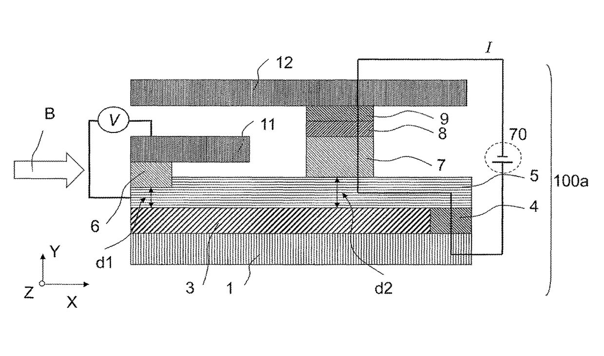
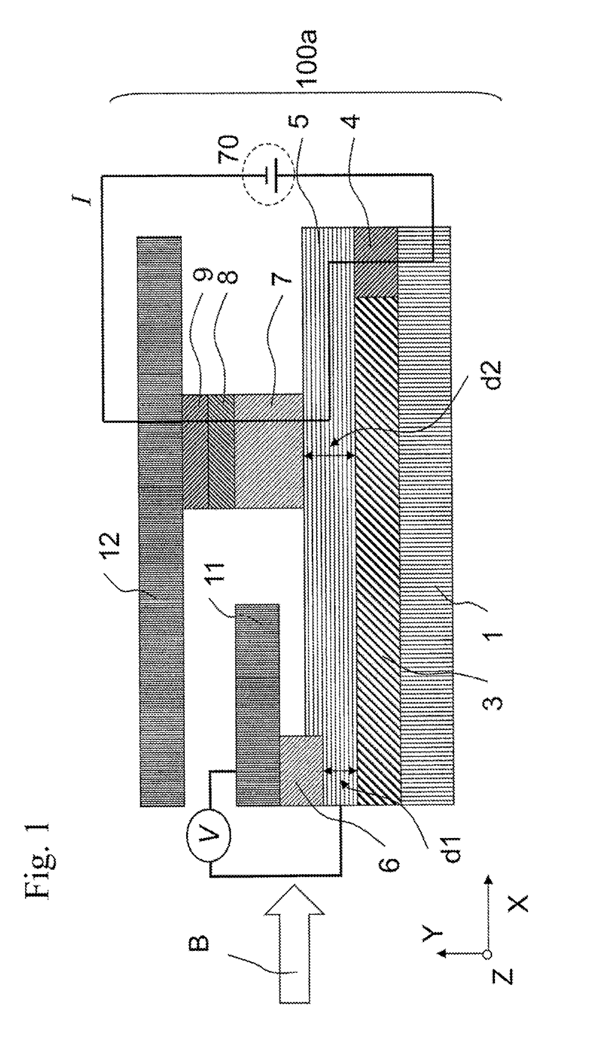
[0028]A magnetic sensor 100a according to a first embodiment of the present invention is described below with reference to FIG. 1.

[0029]The magnetic sensor 100a is placed on a substrate and is covered by a non-magnetic insulating layer made of alumina or the like. As shown in FIG. 1, the magnetic sensor 100a includes a channel layer 5 which accumulates and transports the spins of electrons and which includes a first section and a second section different from the first section, a magnetization free layer 6 placed on the first section of the channel layer 5, and a magnetization-fixed layer 7 placed on the second section of the channel layer 5. The magnetic sensor 100a further includes a lower magnetic shield layer 1, an upper first magnetic shield layer 11 facing the lower magnetic shield layer 1 with the channel layer 5 therebetween, an upper second magnetic shield layer 12 facing the lower magnetic shield layer 1 with the channel layer 5 therebetween, a first insulating layer 3 pla...

second embodiment

[0057]A magnetic head 100A according to a second embodiment of the present invention is described below. After the magnetic sensor 100a according to the first embodiment is prepared, a writing section is formed in the magnetic head 100A. The magnetic sensor 100a according to the first embodiment functions as a reading section in the magnetic head 100A.

[0058]FIG. 5 is a schematic view of the magnetic head 100A. The magnetic head 100A includes the magnetic sensor 100a and a recording head section 100b for writing. In the magnetic head 100A, the magnetic sensor 100a is used in a reading head section. The recording head section 100b includes a return yoke 30, a contact section 32 placed on the return yoke 30, and a main magnetic pole 33 placed above the return yoke 30. The return yoke 30, the contact section 32, and the main magnetic pole 33 form a magnetic flux path. A thin-film coil 31 is placed so as to surround the contact section 32. When a recording current is applied to the thin-...

third embodiment

[0060]FIG. 6 shows a biomagnetic sensor according to a third embodiment of the present invention. The biomagnetic sensor includes a plurality of biomagnetic sensors having the same configuration as that of the magnetic sensor 100a according to the first embodiment. As shown in FIG. 6, the biomagnetic sensor has a structure in which inter-element insulating layers 20 are arranged such that a spin current in each element does not flow into other elements.

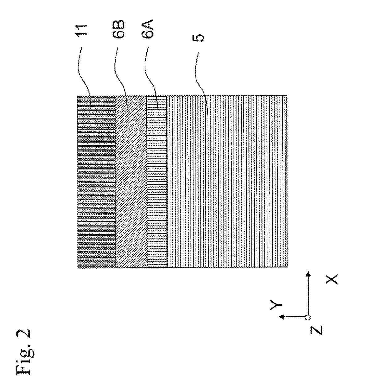
[0061]When a current is applied between a magnetization-fixed layer 7 and channel layers 5, spins are injected into the channel layers 5. The spins injected into the channel layers 5 are transported to first ferromagnetic sub-layers 6B of magnetization free layers 6 and therefore output can be obtained depending on the relative angle between the magnetization direction of the first ferromagnetic sub-layers 6B and the direction of the injected spins. Magnetic flux entering in an X-direction turns the magnetization direction of each fir...


PUM

PropertyMeasurementUnit
thicknessaaaaaaaaaa
thickness d1aaaaaaaaaa
distanceaaaaaaaaaa

Abstract

A magnetic sensor includes a channel layer, a magnetization free layer placed on a first section of the channel layer, and a magnetization-fixed layer placed on a second section of the channel layer. The areal resistance of the interface between the channel layer and the magnetization free layer is lower than the areal resistance of the interface between the channel layer and the magnetization-fixed layer.

Description

BACKGROUND OF THE INVENTION[0001]1. Field of the Invention[0002]The present invention relates to a magnetic sensor, a magnetic head, and a biomagnetic sensor.[0003]2. Description of the Related Art[0004]Magnetoresistive sensors are known as magnetic sensors for use in thin-film magnetic recording / reproducing heads and the like. In general, a magnetoresistive sensor applies a current between a magnetization-fixed layer and a magnetization free layer and therefore provides a high output. However, the magnetoresistive sensor receives a signal, caused by the motion of a domain wall due to current-induced spin torque or the like, unnecessary for magnetic sensors.[0005]Spin accumulation (SA) magnetic sensors each including a magnetization free layer and magnetization-fixed layer formed on the same horizontal surface (a channel layer for accumulating spins) are known (refer to, for example, Japanese Unexamined Patent Application Publication No. 2007-299467 and Japanese Patent No. 4029772)....

Claims


Application Information

Patent Timeline
Patent Type & Authority Patents(United States)
IPC IPC(8): G11B5/39G01R33/09H01L43/08A61B5/05
CPCG01R33/093A61B5/05G11B5/3906G11B5/398G11B5/3929G11B5/3945H01L43/08A61B2562/0223H10N50/10
Inventor SASAKI, TOMOYUKI
Owner TDK CORPARATION
Why Eureka
Try Eureka