Fuel cell system

a fuel cell and system technology, applied in the field of fuel cell systems, can solve the problems of affecting the efficiency of fuel cells, so as to prevent the surging of the turbocompressor, reduce the amount of consumed power of the turbocompressor, and eliminate the dry-up of the fuel cell stack reliably.

Active Publication Date: 2017-08-01
TOYOTA JIDOSHA KK
View PDF8 Cites 0 Cited by
  • Summary
  • Abstract
  • Description
  • Claims
  • Application Information

AI Technical Summary

Benefits of technology

[0010]It is possible to maintain the amount of consumed power of the turbocompressor small and prevent surging of the turbocompressor while reliably eliminating dry-up of the fuel cell stack.

Problems solved by technology

That is, if the turbocompressor is operated with an operating point falling in the surge region, surging is liable to occur in the turbocompressor.

Method used


Image

  • Fuel cell system
  • Fuel cell system
  • Fuel cell system

Examples


Embodiment Construction

s of the Present Invention

[0010]It is possible to maintain the amount of consumed power of the turbocompressor small and prevent surging of the turbocompressor while reliably eliminating dry-up of the fuel cell stack.

[0011]Embodiments of the present invention may be more fully understood from the description of the preferred embodiments as set forth below, together with the accompanying drawings.

BRIEF DESCRIPTION OF THE DRAWINGS

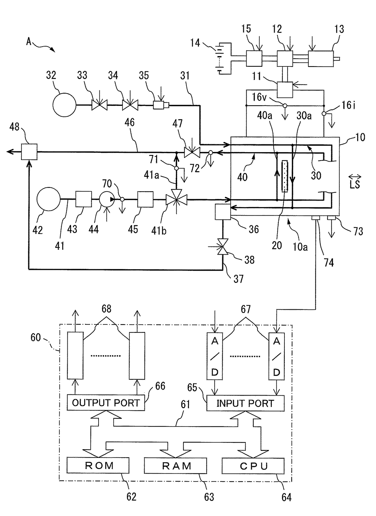
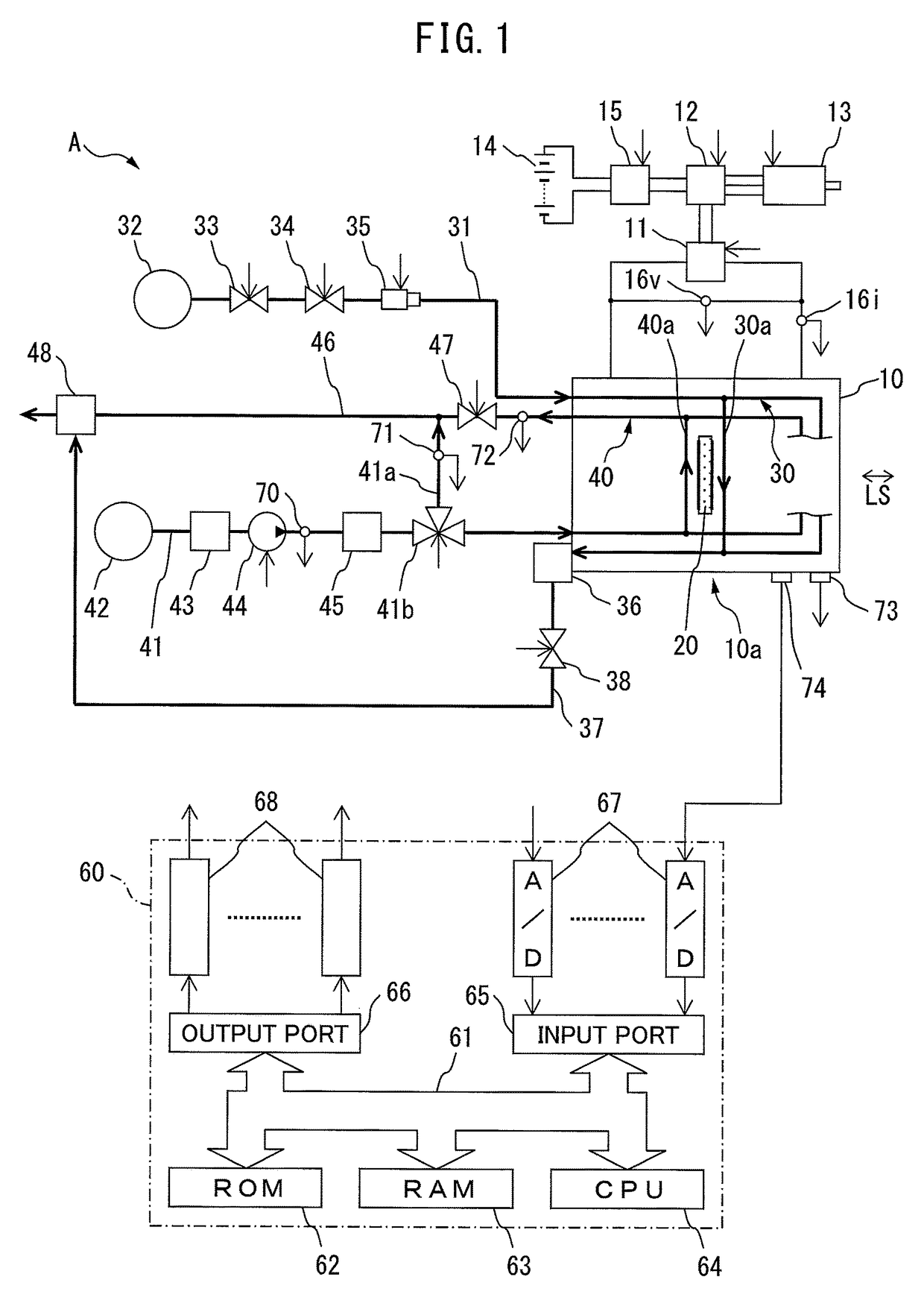
[0012]FIG. 1 is an overview of a fuel cell system.

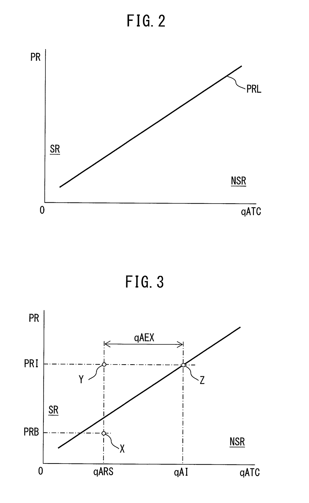
[0013]FIG. 2 is a graph which explains a surge region and nonsurge region of a turbocompressor.

[0014]FIG. 3 is a graph which explains recovery control.

[0015]FIG. 4 is a time chart which explains an embodiment according to the present invention.

[0016]FIG. 5 is a graph which explains a plurality of combinations (PCI,qAI).

[0017]FIG. 6 is a view which shows a man of the combinations (PCI,qAI).

[0018]FIG. 7 is a flowchart which shows a routine for performing system control.

[0019]FIG. 8 is a flowchart which shows a r...


PUM

PropertyMeasurementUnit
pressureaaaaaaaaaa
pressure ratioaaaaaaaaaa
temperatureaaaaaaaaaa

Abstract

When it is judged that a fuel cell stack is drying up, recovery control is performed. In recovery control, the cathode pressure control valve is controlled so that the cathode pressure becomes an increased cathode pressure, a discharge flow rate of air of a turbocompressor is set to an increased flow rate of air, and a bypass control valve is controlled so that a flow rate of air which is fed to the fuel cell stack is maintained at the requested flow rate of air. Furthermore, a combination of an increased cathode pressure and increased flow rate of air for minimizing the amount of consumed power of the turbocompressor required for eliminating dry-up is set based on the requested flow rate of air of the fuel cell stack.

Description

RELATED APPLICATIONS[0001]This application claims the benefit of JP Application No. 2014-225638 filed Nov. 3, 2014, the entire disclosure of which is incorporated by reference herein.TECHNICAL FIELD[0002]The present invention relates to a fuel cell system.BACKGROUND ART[0003]A fuel cell system is known in the art which is provided with a fuel cell stack which generates electricity by an electrochemical reaction between a fuel gas and oxidant gas, an oxidant gas feed pipe which is connected to an inlet of an oxidant gas passage which is formed in the fuel cell stack, a turbocompressor which is arranged in the oxidant gas feed pipe and which feeds oxidant gas, a bypass pipe which branches off from the oxidant gas feed pipe downstream of the turbocompressor, a bypass control valve which controls the amount of oxidant gas which is discharged from the turbocompressor and fed to the fuel cell stack and the amount of oxidant gas which is discharged from the turbocompressor and flows into t...

Claims


Application Information

Patent Timeline
Patent Type & Authority Patents(United States)
IPC IPC(8): H01M8/04H01M8/04111H01M8/04492H01M8/04537H01M8/04746
CPCH01M8/04111H01M8/04492H01M8/04559H01M8/04649H01M8/04753H01M8/04776H01M8/04097Y02E60/50
Inventor ILO, ATSUO
Owner TOYOTA JIDOSHA KK
Why Eureka
Try Eureka