Control method of magnetic solenoid valve, control method of electromagnetically controlled inlet valve of high pressure fuel pump, and control device for electromagnetic actuator of electromagnetically controlled inlet valve
a technology of electromagnetic actuator and electromagnetic solenoid valve, which is applied in the direction of electric control, piston pumps, positive displacement liquid engines, etc., to achieve the effects of reducing noise caused by impingement, consuming current, and reducing consumption curren
- Summary
- Abstract
- Description
- Claims
- Application Information
AI Technical Summary
Benefits of technology
Problems solved by technology
Method used
Image
Examples
first embodiment
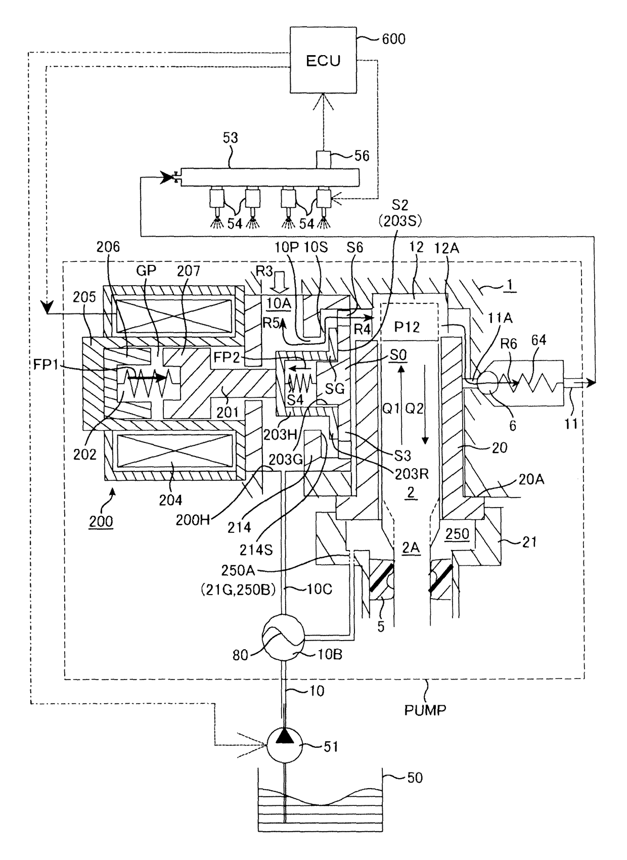
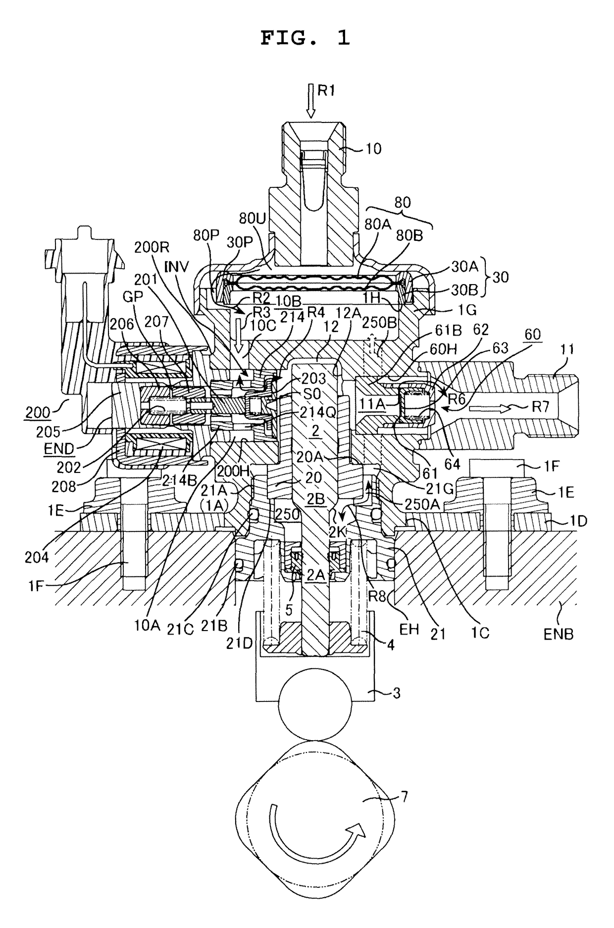
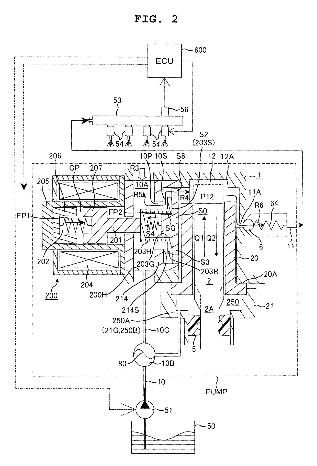
[0024]The first embodiment of a high pressure fuel pump in which the present invention is carried out is explained in conjunction with FIG. 1 to FIG. 5. Symbols cannot be given to detailed parts in FIG. 1 and hence, symbols used in the explanation which are not described in FIG. 1 are described in enlarged views including FIG. 2 and succeeding drawings.
[0025]A recessed portion 12A which forms a bottomed cylindrical space with one end open is formed on a pump housing 1, and a cylinder 20 is inserted into the recessed portion 12A from an open end side. A gap between an outer periphery of the cylinder 20 and the pump housing 1 is sealed by a pressure contact portion 20A. A piston plunger 2 is slidably fitted into the cylinder 20 and hence, a gap between an inner peripheral surface of the cylinder 20 and an outer peripheral surface of the piston plunger 2 is sealed by fuel which intrudes between both slide fitting surfaces. As a result, a pressurizing chamber 12 is formed between a dist...
second embodiment
[0087]FIG. 7 shows a second embodiment. A high pressure fuel pump of this embodiment is equal to the high pressure fuel pump of the first embodiment in constitution. In the second embodiment, a current supply period is switched to a limited current supply period while a plunger rod 201 moves in the valve closing direction. By lowering a current value to, for example, a value close to a holding current during the movement of the plunger rod 201, a magnetic attraction force is reduced so that a moving speed of the plunger rod 201 is lowered compared to a moving speed of the plunger rod 201 in the first embodiment. As a result, noises which are generated when an anchor 207 impinges on a fixed core 206 are reduced.
[0088]To consider a case where only a limited current is given without supplying a first current, a magnetic attraction force larger than a biasing force of a plunger rod biasing spring is not generated thus giving rise to a possibility that the plunger rod 201 cannot be moved...
third embodiment
[0092]FIG. 8 shows a third embodiment. In this embodiment, a high current is initially given in a 1st current supply period and, thereafter, the current value is lowered. Due to such an operation, the movement of a plunger rod 201 can be surely started by giving a high current initially. Further, a period during which a high current value is given can be shortened and hence, a heating value of a solenoid is not largely increased. This embodiment is advantageously applicable to a case where a current value cannot be accurately controlled or a case where it is necessary to take a large margin in an operational current.
[0093]In this embodiment, although a current value in the 1st current supply period is not a fixed value, a peak current never fails to become larger than a current value necessary for an operation of attracting a plunger rod 201 (an electric current which makes a magnetic attraction force larger than a biasing force of a plunger rod biasing spring).
[0094]In this embodim...
PUM
 Abstract
Description
Claims
Application Information
 - R&D
- Intellectual Property
- Life Sciences
- Materials
- Tech Scout
- Unparalleled Data Quality
- Higher Quality Content
- 60% Fewer Hallucinations
Browse by: Latest US Patents, China's latest patents, Technical Efficacy Thesaurus, Application Domain, Technology Topic, Popular Technical Reports.
© 2025 PatSnap. All rights reserved.Legal|Privacy policy|Modern Slavery Act Transparency Statement|Sitemap|About US| Contact US: help@patsnap.com


