
Stone dumping real time measuring system for stone dumping vessel

a real-time measuring and stone dumping technology, applied in the field of measuring systems, can solve the problems of poor measurement accuracy, inconvenient operation, and inability to accurately measure the accuracy and achieve the effect of improving the accuracy and precision of the stone real-time measuring system

Active Publication Date: 2017-08-15
SHIP & OCEAN INDUSTRIES R&D CENTER
View PDF2 Cites 4 Cited by
  • Summary
  • Abstract
  • Description
  • Claims
  • Application Information

AI Technical Summary

Benefits of technology

The present invention provides a system for measuring the amount of stones being dumped from a vessel in real-time. The system includes a floater that moves on the water and is positioned accurately using a positioning device. The system also includes a surge compensator that corrects any errors in the depth sounder readings, resulting in more accurate and precise measurements. Overall, this system allows for the efficient and accurate measurement of stone dumping.

Problems solved by technology

However, the above-mentioned stone dumping measuring system can measure and report the stone dumping result, but since the measuring system is directly installed on the hull of the stone dumping vessel, the stone dumping measuring system measuring system may be interfered by the six-dimensional motion of the hull.
As a result, the measuring result of the stone dumping measuring system is not accurate, and the measurement accuracy is not good.
If the user wants to correct the measurement accuracy, it is necessary to invest a high-cost sensing apparatus and computing software to make the stone dumping measuring system more complicated and costly.

Method used


Image

  • Stone dumping real time measuring system for stone dumping vessel
  • Stone dumping real time measuring system for stone dumping vessel
  • Stone dumping real time measuring system for stone dumping vessel

Examples


Embodiment Construction

[0011]Embodiments of the present invention will now be described, by way of example only, with reference to the accompanying drawings.

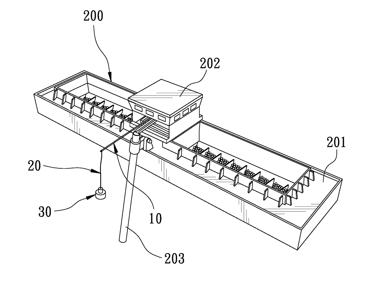
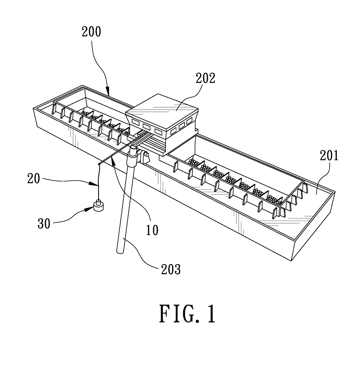
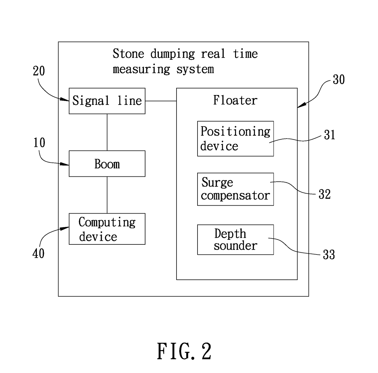
[0012]FIG. 1 is a perspective view of the present invention mounted to a stone dumping vessel. FIG. 2 is a block diagram of a stone dumping real time measuring system of the present invention. The present invention discloses a stone dumping real time measuring system for a stone dumping vessel. The stone dumping real time measuring system is applied to a stone dumping vessel 200. The stone dumping vessel 200 has a hull 201, a control cabin 202 at the center of the hull 201, and a fallpipe 203 located on the hull 201 close to the control cabin 202. The mouth of the fallpipe 203 is aligned with a predetermined stone dumping position when in use. The stone dumping real time measuring system is mounted to the control cabin 202, and comprises a boom 10, a signal line 20, a floater 30, and a computing device 40.

[0013]The boom 10 is mounted to the control ca...


PUM


Abstract

A stone dumping real time measuring system for a stone dumping vessel includes a boom. The boom is mounted to a control cabin of the stone dumping vessel and can extend outwardly from the control cabin to be located above a predetermined stone dumping position. A signal line hangs from the boom. A floater is connected to the other end of the signal line. The floater is provided with a positioning device, a surge compensator, and a depth sounder. The floater freely floats on the water through the separate design of the floater and the stone dumping vessel. The floater is directly positioned by the positioning device of the floater, and the surge compensator is able to correct a measurement error of the depth sounder to instantly report the stone dumping result and to improve the accuracy and precision of the stone real time measuring system.

Description

FIELD OF THE INVENTION[0001]The present invention relates to a measuring system, and more particularly to a stone dumping real time measuring system for a stone dumping vessel.BACKGROUND OF THE INVENTION[0002]A conventional stone dumping measuring system comprises a measuring frame. The measuring frame is placed in the water from the side of the hull to measure and report the stone dumping result when the stone dumping operation of the stone dumping vessel is completed.[0003]However, the above-mentioned stone dumping measuring system can measure and report the stone dumping result, but since the measuring system is directly installed on the hull of the stone dumping vessel, the stone dumping measuring system measuring system may be interfered by the six-dimensional motion of the hull. As a result, the measuring result of the stone dumping measuring system is not accurate, and the measurement accuracy is not good. If the user wants to correct the measurement accuracy, it is necessary...

Claims


Application Information

Patent Timeline
IPC IPC(8): B63B35/44G01S15/08B63B27/16B63B39/00G01S7/52
CPCB63B27/16B63B35/44B63B39/005G01S15/08B63B2213/02B63B2211/02G01S7/52004B63B27/28G01S15/88
Inventor CHEN, LIN-FU
Owner SHIP & OCEAN INDUSTRIES R&D CENTER
Learn More