Traveling device and working machine

a traveling device and working machine technology, applied in mechanical machines/dredgers, soil-shifting machines/dredgers, transportation and packaging, etc., can solve problems such as damage to the travel motor hydraulic pipe, damage to the piping cover described in patent documents 1 and 2, and prevent damag

Inactive Publication Date: 2017-08-15
CATEPILLAR SARL
View PDF27 Cites 1 Cited by
  • Summary
  • Abstract
  • Description
  • Claims
  • Application Information

AI Technical Summary

Benefits of technology

[0015]The present invention is made in view of these points, and an object of the present invention is to provide a traveling device that can reduce the risk that the travel motor hydraulic pipe and the piping cover collide with the obstacle, and enable the operation of assembling the travel motor hydraulic pipe to be easily performed, and to a working machine including the traveling device.
[0021]In the invention according to claim 2, the long hole is formed in the upper surface plate along the expanded portion formed by expanding the upper surface plate of the travel frame toward the side of the vehicle center. Thus, the support attachment unit of the piping support that holds the travel motor hydraulic pipe located in the long hole can be positioned at any portion around the long hole including a portion on the expanded portion of the upper surface plate. The travel motor hydraulic pipe can be held at a predetermined portion in the long hole by the piping support attached to the support attachment unit. Thus, the pipe can be prevented from being damaged by friction with an edge of the long hole and the like.
[0022]In the invention according to claim 3, the long hole is formed in the upper surface plate along the expanded portion formed by expanding the upper surface plate of the travel frame toward the side of the vehicle center. Thus, the cover attachment unit of the piping cover can be provided at any portion around the long hole including a portion on the expanded portion of the upper surface plate. The expanded portion of the upper surface plate can block the obstacle such as a rock protruding upward from below and thus can protect the piping cover. The piping cover is attached over the center frame positioned above the travel frame and the cover attachment unit on the upper surface plate of the travel frame. Thus, the entire piping cover is positioned above the upper surface plate of the travel frame. All things considered, the piping cover can be prevented from colliding with the obstacle such as a rock at a portion other than the expanded portion.
[0023]In the invention according to claim 4, in the working machine, in which the working apparatus is mounted on the vehicle, the risk that the travel motor hydraulic pipe and the piping cover collide with the obstacle such as a rock when the working machine travels can be reduced. Furthermore, the operation for assembling the travel motor hydraulic pipe can be easily performed. Thus, with the expanded portion, the long hole required for the pipe routing can be secured without lowering the rigidity of the travel frame. The expanded portion can block the obstacle such as a rock protruding upward from below, and thus can prevent the travel motor hydraulic pipe and the piping cover from being damaged. With the long hole, the pipe routing enabling the travel motor hydraulic pipe to be smoothly routed from the center frame to the travel motor attachment unit can be secured.

Problems solved by technology

However, the piping covers described in Patent Documents 1 and 2 might be damaged or deform by colliding with a large obstacle.
This might lead to damage on the travel motor hydraulic pipe and a problem regarding a vehicle outer shape.
Thus, the piping cover needs to have a size large enough to accept the extra length of the bent pipes, and thus has larger chance of colliding with the obstacle.
Therefore, the piping cover is likely to be damaged and deform, and the travel motor hydraulic pipe in the cover might also be damaged.
The configurations can prevent the travel motor hydraulic pipe from being damaged, but have a problem that an operation for assembling the hydraulic pipe is difficult to perform.
In an attempt to solve this problem, for example, further problems arise.
Specifically, the configuration in Patent Document 5 requires structurally difficult changes such as forming hole a large enough to allow a hand to be put into the hose insertion space, and providing a pipe guide surface in the hose insertion space.

Method used


Image

  • Traveling device and working machine
  • Traveling device and working machine
  • Traveling device and working machine

Examples


Embodiment Construction

[0030]The present invention is described below in detail based on an embodiment shown in FIGS. 1 to 5.

[0031]FIG. 5 shows a hydraulic shovel as a working machine 11. The working machine 11 includes a vehicle 12 and a working apparatus 13. In the vehicle 12, an upper swiveling body 12sw is disposed on a traveling device 12tr at a lower portion in such a manner as to be capable of swiveling through a swivel bearing. The working apparatus 13 is mounted on the upper swiveling body 12sw of the vehicle 12. In the working apparatus 13, a stick 13sty that is rotated by a stick cylinder 13stc is coupled to a distal end portion of a boom 13bm that is rotated in an up and down direction by a boom cylinder 13bmc. A bucket 13bk that is rotated by a bucket cylinder 13bkc is coupled to a distal end portion of the stick 13st.

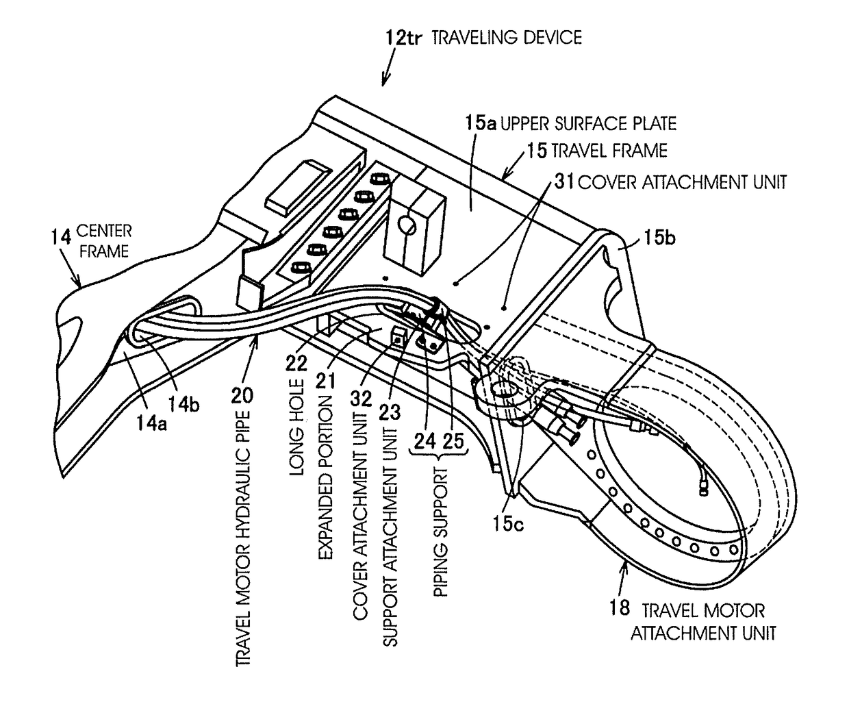
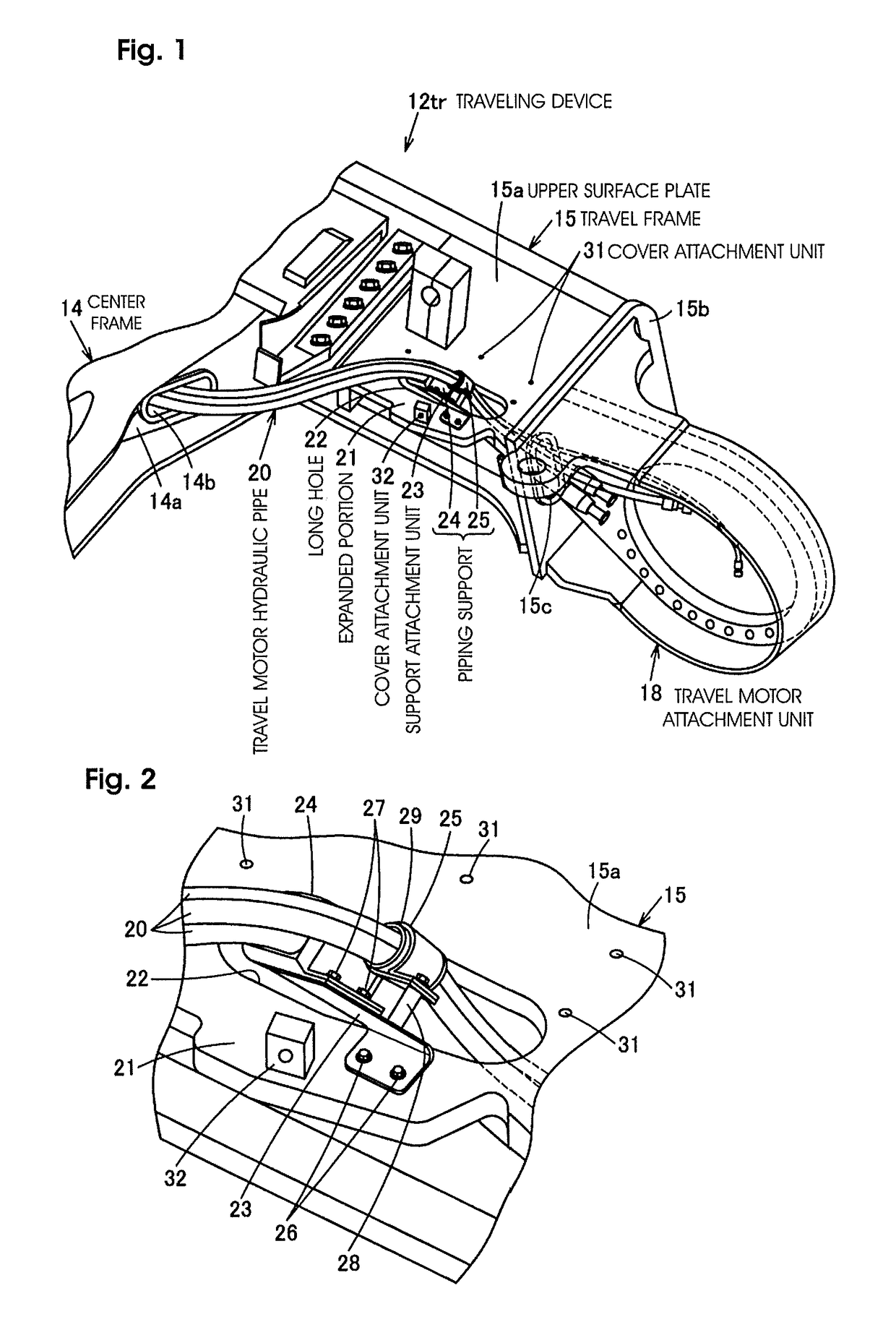
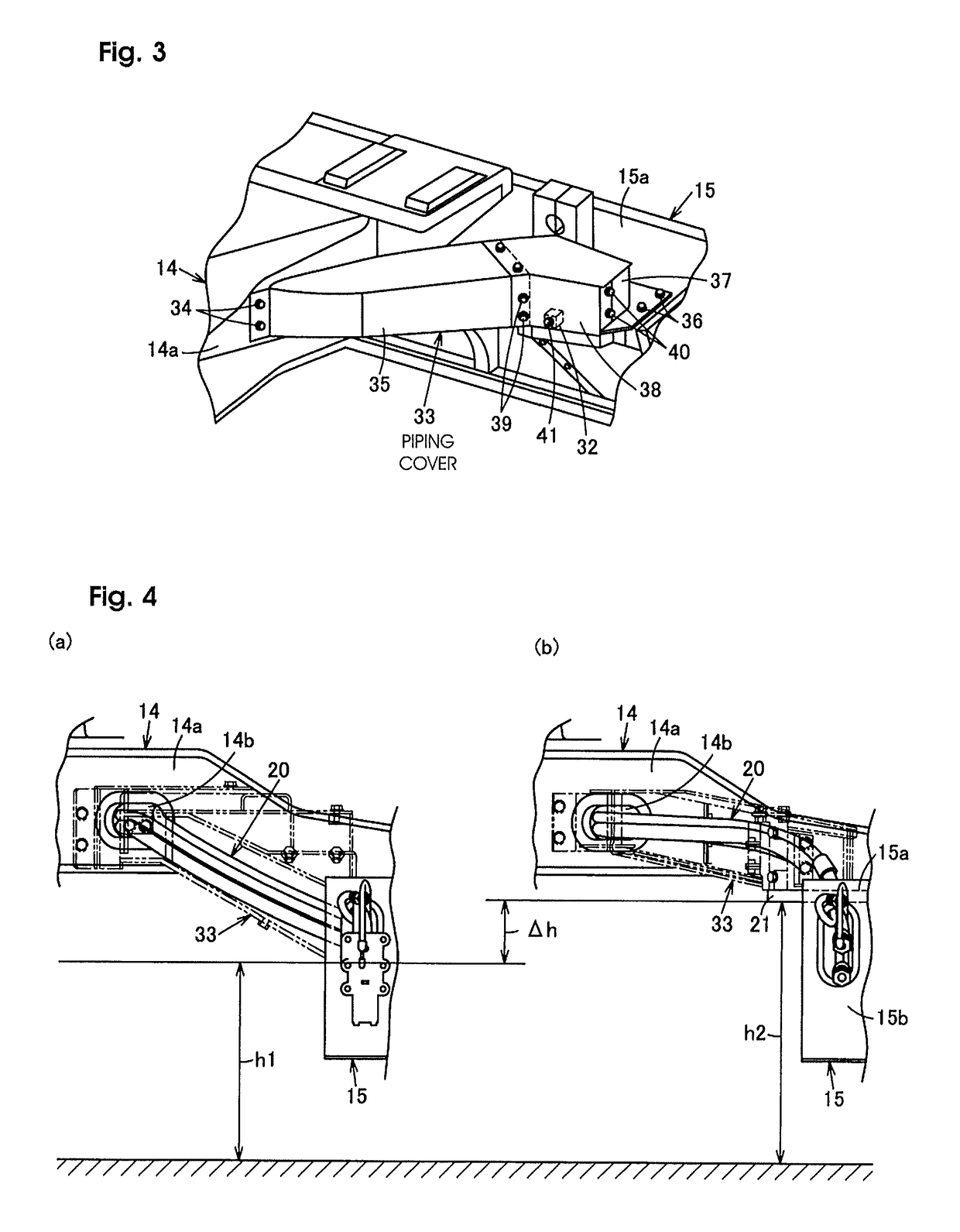
[0032]The traveling device 12tr at the lower portion includes a center frame 14, travel frames (what is known as truck frames) 15, crawler belts 17, travel motor attachment uni...


PUM


Abstract

A travelling frame of a travelling device positioned between a center frame and a travelling motor attachment portion includes an upper plate extended toward the center side of the vehicle to form an extended portion. A long hole into which travelling motor hydraulic piping is inserted is formed in the upper plate along the extended portion. The travelling motor hydraulic piping extends from a lead-out hole opened in an end plate of the center frame, through the long hole of the upper plate and a long hole opened in an end plate, and inserted into the travelling motor attachment portion.

Description

CROSS-REFERENCE TO RELATED APPLICATIONS[0001]This application is a national phase application of International Patent Application No. PCT / EP2014 / 075396, filed Nov. 24, 2014, which claims priority to Japanese Patent Application No. 2013-246537, filed Nov. 28, 2013, both of which are incorporated by reference herein in their entireties for all purposes.TECHNICAL FIELD[0002]The present invention relates to a crawler type traveling device and a working machine including the traveling device.BACKGROUND ART[0003]As shown in FIG. 6, a traveling device 1 provided at a lower portion of a hydraulic shovel is configured such that: upper surface plates 4 of travel frames 3 for attaching crawler belts are integrally provided on both left and right sides of a center frame 2 positioned at a vehicle center; a travel motor attachment unit 5 is integrally provided on one end side of the travel frame 3; and the crawler belt (not shown) attached along the travel frame 3 is driven to rotate by a crawler...

Claims


Application Information

Patent Timeline
Patent Type & Authority Patents(United States)
IPC IPC(8): E02F9/22B62D55/125B62D55/06E02F9/02B62D55/08E02F3/32E02F9/08B60K7/00B60K17/10
CPCE02F9/02B60K7/0023B62D55/06B62D55/08B62D55/125E02F3/32E02F9/0808E02F9/22E02F9/2275B60K7/0015B60K17/10B60Y2200/25B60Y2200/412E02F9/226
Inventor MIYATA, KAZUHISAIZAWA, MICHIHIROIMAGAWA, MASAMITSUKIDOGUCHI, SHUJI
Owner CATEPILLAR SARL
Why Eureka
Try Eureka