Apparatus for determining the angle between two planar workpiece surfaces

a technology for workpiece surfaces and angles, applied in angle measurement, manufacturing tools, instruments, etc., can solve the problems of disadvantageous effort required for this purpose, disadvantageous constructive effort caused by transmitters and receiving devices, etc., and achieve simple constructive means and high-resolution angular detection

Active Publication Date: 2017-08-15
KEBA AG
View PDF13 Cites 0 Cited by
  • Summary
  • Abstract
  • Description
  • Claims
  • Application Information

AI Technical Summary

Benefits of technology

[0007]The invention is thus based on the object of providing an apparatus for determining the angle between two planar workpiece surfaces in such a way that high-resolution angular detection can be ensured with comparatively simple constructive means.
[0009]The photo diodes that are used as monitor diodes in laser transmitters are usually used for the power control of the laser diodes because the photocurrent of said monitor diodes subjected to laser light depends on the emitted light power of the laser diode. When using the monitor diode as a receiver for the reflected laser beam, the monitor diode, when receiving a reflected laser beam, is not only subjected to the transmitted laser beam but also by the reflected laser beam, which is indicated in a considerable rise in the photocurrent, so that the rotational angle of the straightening rotor can be used as a measure for the inclination of a normal on the respective work piece surface during the occurrence of such a current peak of the monitor diode. A separate receiving device for the laser beam can thus be avoided and leads to a simple, compact construction, which is especially relevant in the constricted space in the region of the bending dies of folding presses.

Problems solved by technology

The effort required for this purpose is disadvantageous, since a respective measuring device is required for each limb for measuring the angle between the two limbs of the sheet.
The constructive effort caused by the transmitter and receiving device is disadvantageous however, which constructive effort requires in the beam path between the laser transmitter and the straightening rotor a semi-transparent mirror for deflecting the reflected laser beam to the receiving device and thus requires special constructions of the bending die of folding presses in order to house the measuring apparatus.

Method used


Image

  • Apparatus for determining the angle between two planar workpiece surfaces
  • Apparatus for determining the angle between two planar workpiece surfaces
  • Apparatus for determining the angle between two planar workpiece surfaces

Examples


Embodiment Construction

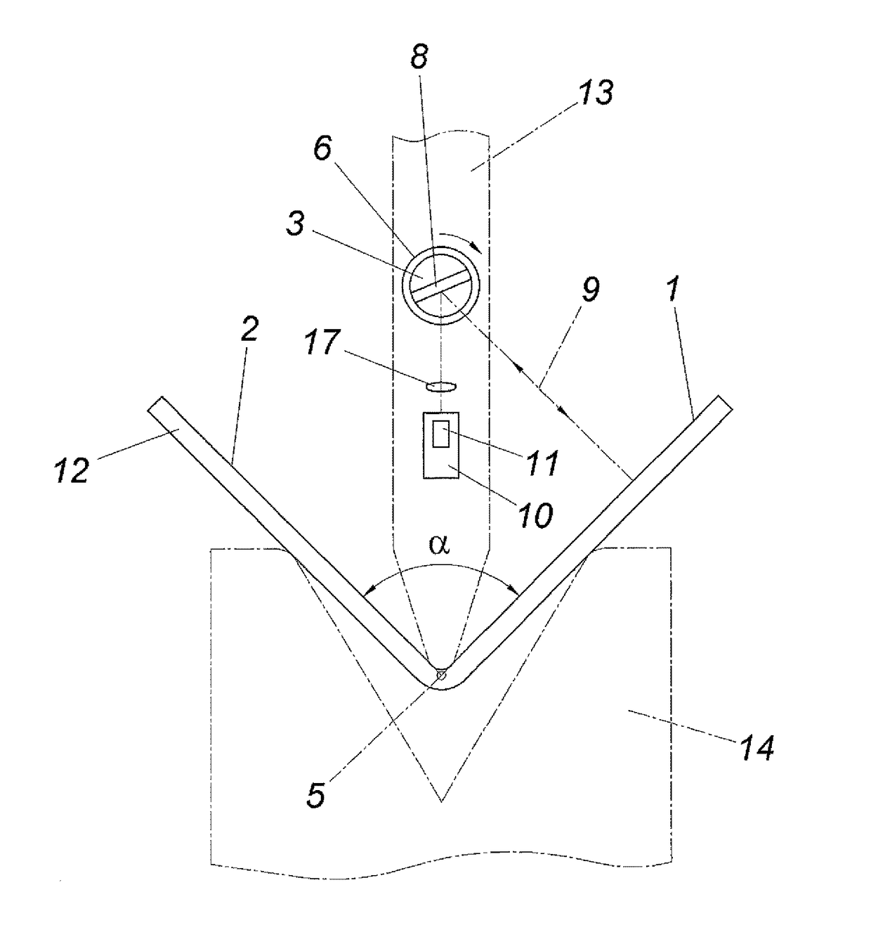
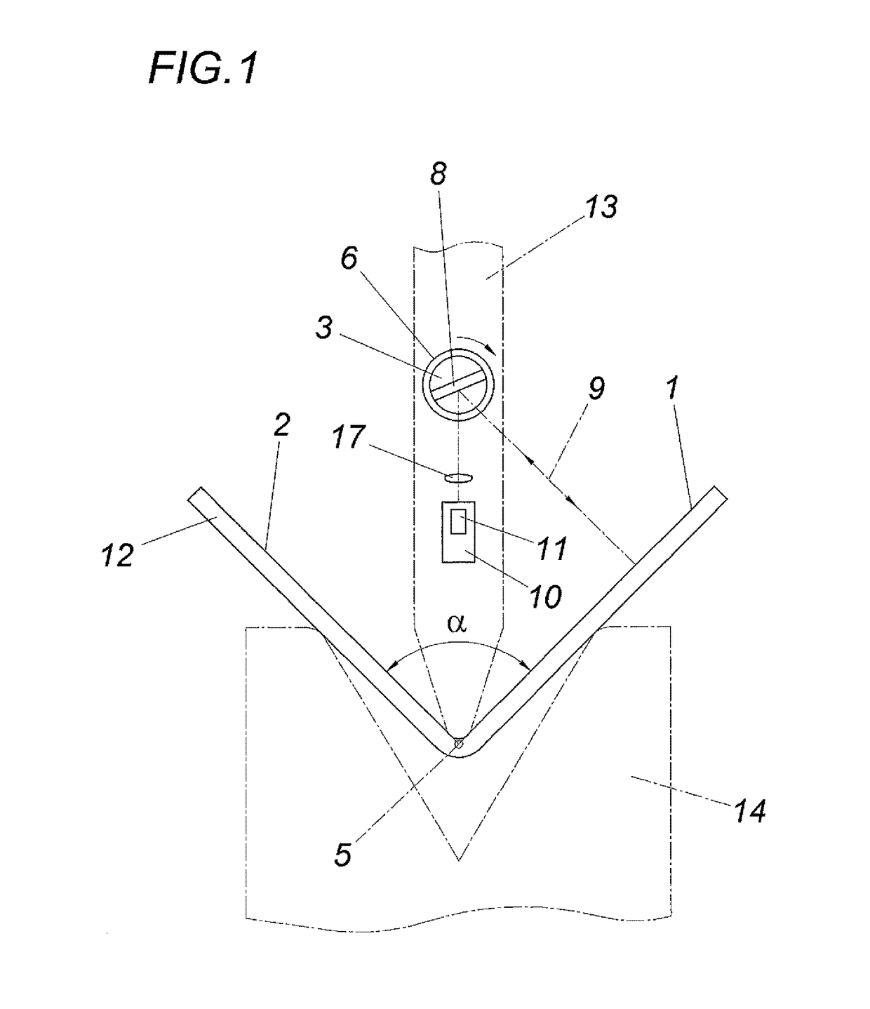
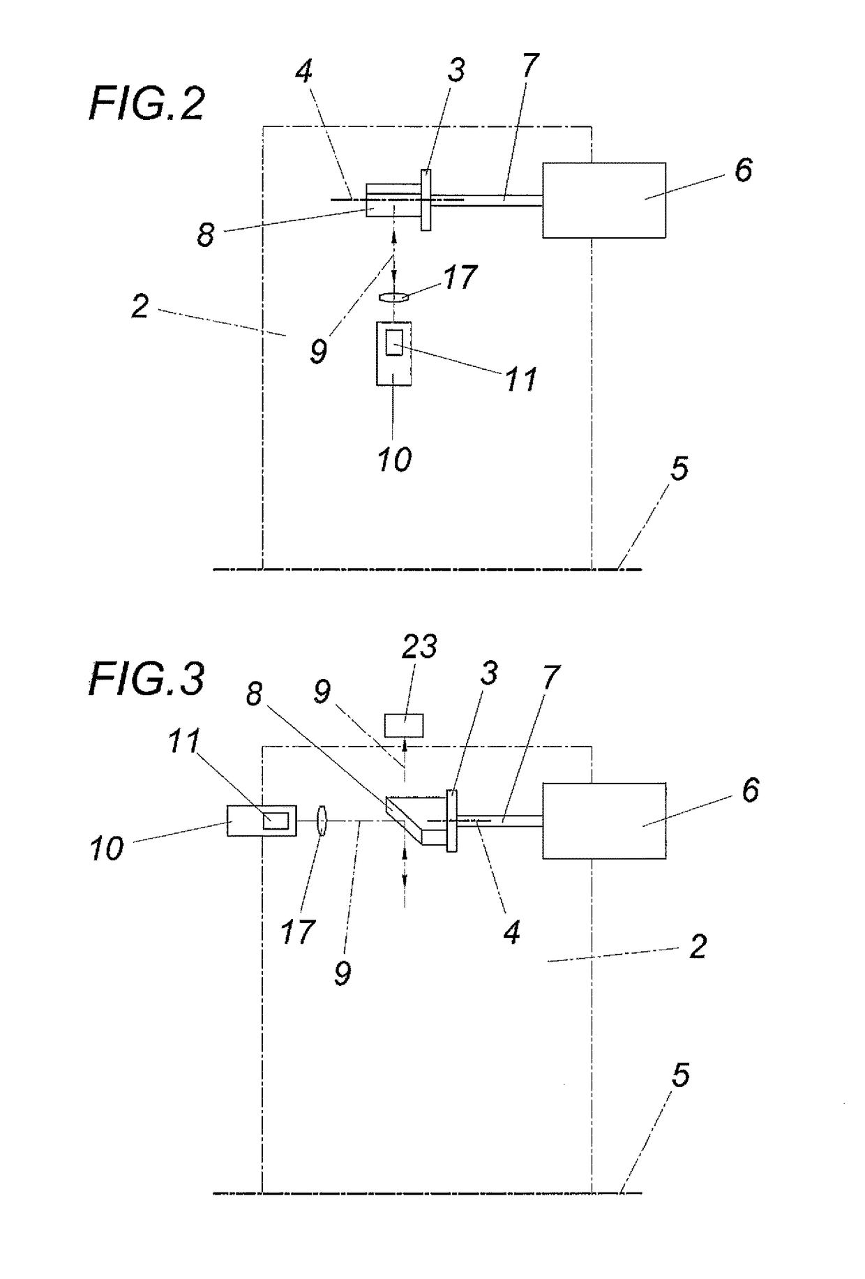
[0018]As is shown especially in FIGS. 1 and 2, an apparatus in accordance with the invention for determining the angle α between two planar workpiece surfaces 1, 2 comprises a straightening rotor 3 whose axis 4 extends parallel to the vertex axis 5 of the angle α to be measured. In the illustrated embodiment, the straightening rotor 3 which can be driven by a motor 6 via a shaft 7 comprises a flat reflection surface 8 extending in the direction of the rotor axis 4 for a laser beam 9 which is emitted by a static laser transmitter 10 and impinges in a focused manner on the reflection surface 8 of the straightening rotor 3 in order to be mirrored on the reflection surface 8. The laser beam 9 emitted from the reflection surface 8 moves over the two workpiece surfaces 1, 2 along straight lines which are perpendicular to the vertex axis 5, intersect in the vertex axis 5 and enclose the angle α between themselves. The laser beam 9 which impinges on the workpiece surfaces 1 and is emitted b...


PUM

PropertyMeasurementUnit
angleaaaaaaaaaa
angleaaaaaaaaaa
bending angleaaaaaaaaaa

Abstract

The invention relates to an apparatus for determining the angle (α) between two planar workpiece surfaces (1, 2), comprising a laser transmitter (10) for a laser beam (9), a continuously rotating straightening rotor (3), which is arranged between the two workpiece surfaces (1, 2), is axially parallel to the vertex axis (5) of the angle (α) and has an emission direction for the laser beam (9) that is perpendicular to the rotor axis (4), and comprising a receiving device (11) having a receiver for the laser beam (9) reflected on the workpiece surfaces (1, 2) in the emission direction, and an evaluation circuit (18) connected to the receiving device (11). In order to provide advantageous constructive conditions, it is proposed that the laser transmitter (10) comprises a monitor diode (16) and that the monitor diode (16) forms the receiver for the reflected laser beam (9).

Description

CROSS REFERENCE TO RELATED APPLICATIONS[0001]This application is the National Stage of PCT / AT2015 / 050162 filed on Jun. 26, 2015, which claims priority under 35 U.S.C. §119 of Austrian Application No. A 50447 / 2014 filed on Jun. 27, 2014, the disclosure of which is incorporated by reference. The international application under PCT article 21(2) was not published in English.[0002]1. Field of the Invention[0003]The invention relates to an apparatus for determining the angle between two planar workpiece surfaces, comprising a laser transmitter for a laser beam, a continuously rotating straightening rotor, which is arranged between the two workpiece surfaces, is axially parallel to the vertex axis of the angle and has an emission direction for the laser beam that is perpendicular to the rotor axis, and comprising a receiving device having a receiver for the laser beam reflected on the workpiece surfaces in the emission direction, and an evaluation circuit connected to the receiving device...

Claims


Application Information

Patent Timeline
Patent Type & Authority Patents(United States)
IPC IPC(8): G01B11/26G01C1/00B21D5/02B21C51/00
CPCG01B11/26B21C51/00B21D5/02G01B9/10B21D5/00B21D5/0209B21D5/006
Inventor WOEGERBAUER, ANDREASWOEGERBAUER, JOHANN
Owner KEBA AG
Why Eureka
Try Eureka