Moisture detection element, exhaled gas detection device, exhaled air inspection system, and dew condensation removal method

a technology of exhaled gas and moisture detection element, which is applied in the direction of measurement devices, scientific instruments, instruments, etc., can solve the problems of not having the capability to check whether introduced air is present, the device does not have a function, and the detection delay of moisture becomes smaller, and the robustness of the moisture detection element 1 can be improved. , the effect of speeding up the detection

Active Publication Date: 2021-03-09
HITACHI LTD
View PDF8 Cites 0 Cited by
  • Summary
  • Abstract
  • Description
  • Claims
  • Application Information

AI Technical Summary

Benefits of technology

[0103]In the cases of the moisture detection element 1b shown in FIG. 7B and the moisture detection element 1e shown in FIG. 7E, the same advantageous effects can be achieved.
[0104]Here, in the moisture detection element 1 according to the present embodiment, as shown in FIG. 2 and FIG. 3, the AC voltage vi is used as an applied voltage. With the use of the AC voltage vi, the measurement performed by the moisture detection element 1 according to the present embodiment can be speeded up. In other words, if a DC voltage is used as the applied voltage, a delay occurs in the rising edge of the applied voltage due to a capacitance component in an equivalent circuit formed by the moisture detection element 1 and moisture. Therefore, a delay occurs in the detection of the moisture. On the other hand, if the AC voltage vi is used as the applied voltage, an influence due to a capacitance component in the equivalent circuit becomes smaller, and therefore a delay in the detection of the moisture becomes smaller. Particularly, to use a high frequency (several MHz) as the frequency of the AC voltage vi, which works as the applied voltage, makes it possible to speed up the detection.
[0106]FIG. 8 is a diagram for explaining a dew condensation removal method executed by the moisture detection element 1 according to the present embodiment. Here, FIG. 8 is a cross-sectional schematic view taken along the line D-D in FIG. 1.
[0107]Because FIG. 8 is the same diagram as FIG. 3, the components in FIG. 8 are given the same reference signs as those given to the components in FIG. 3, and the explanation about these components is omitted.
[0108]A state of dew condensation in this case is a state in which, as shown in FIG. 8, water molecules 11 have already adhered to the insulating portion 4 before exhaled air is introduced, and conduction is established between the voltage-applied electrode 2 and the detection electrode 3 via the water molecules 11 and the conductive film 6.
[0109]In such a case, a potential difference between a DC voltage Vi applied to the voltage-applied electrode 2 and an output voltage Vo is small. The output voltage Vo is a DC voltage. In the case where the potential difference between the DC voltage Vi and the output voltage Vo is small before exhaled air is introduced, the power supply 5 applies a constant DC current to the voltage-applied electrode 2 (refer to a bold arrow in FIG. 8). In actuality, the power supply 5 applies an AC current biased by a DC component to the voltage-applied electrode 2. Here, it will be assumed that a lowercase character such as “v” is used for representing AC voltages, and an uppercase character such as “V” is used for representing DC voltages in the present embodiment.

Problems solved by technology

This alcohol inspection device does not have a function to judge whether the exhaled air is air exhaled by a person or not, and therefore there is a possibility that deceiving or the like is made by inspiring the ambient air instead of the air exhaled by the person.
Therefore, the alcohol detection device disclosed in Patent Literature 1 is not a device installed for judging whether introduced air is the exhaled air of a person or not by detecting saturated vapor.
In addition, because the alcohol detection device disclosed in Patent Literature 1 includes a fan, it cannot be downsized, so that it is not suitable for being given mobility.
Furthermore, because the alcohol detection device disclosed in Patent Literature 1 does not detect saturated vapor, it does not have sufficient capability to check whether introduced air is the exhaled air of a person being tested or not.
In addition, if it is tried to achieve the portability of an alcohol inspection device by making the alcohol inspection device a downsized and low power consumption type device, it becomes necessary to use micropattern electrodes, which leads to the occurrence of sensor errors due to dust in the air.
In addition, if a heater layer is introduced as an anti-dew concentration measure, the process cost is increased due to this newly-needed heater layer

Method used


Image

  • Moisture detection element, exhaled gas detection device, exhaled air inspection system, and dew condensation removal method
  • Moisture detection element, exhaled gas detection device, exhaled air inspection system, and dew condensation removal method
  • Moisture detection element, exhaled gas detection device, exhaled air inspection system, and dew condensation removal method

Examples


Embodiment Construction

[0054]Next, a configuration for realizing the invention (hereinafter, referred to as the embodiment) will be explained in detail accordingly with reference to the accompanying drawings.

[0055]“Moisture Detection Element 1”

(Structure of Moisture Detection Element 1)

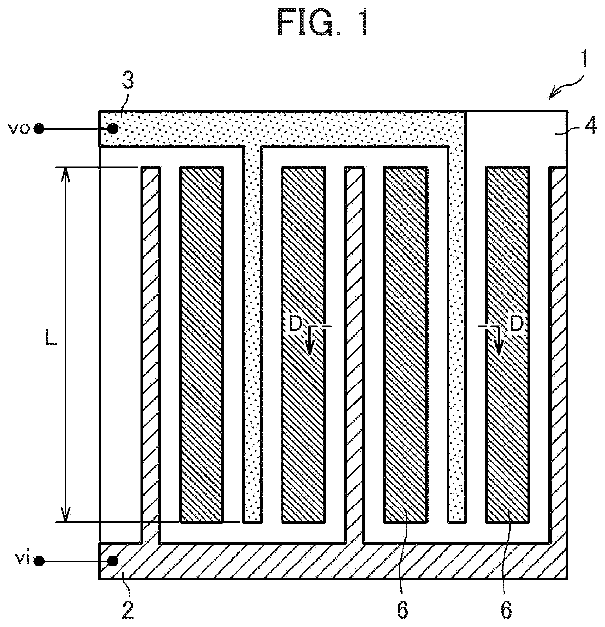
[0056]FIG. 1 is a diagram showing the structure of a moisture detection element 1 according to the present embodiment.

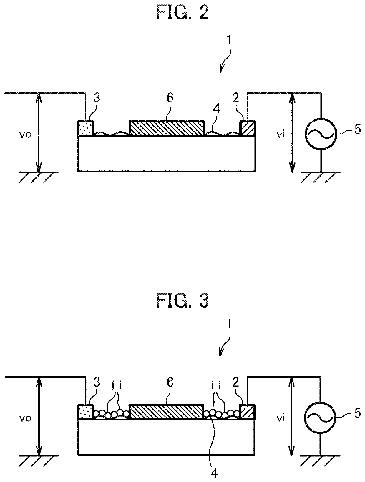
[0057]As shown in FIG. 1, the moisture detection element (the moisture detection unit) 1 is connected to a power supply 5 (refer to FIG. 2 and FIG. 3), and includes: a voltage-applied electrode (a voltage-applied portion) 2; a detection electrode (an output portion) 3; conductive films (conductive portions) 6; and an insulating portion 4.

[0058]The voltage-applied electrode 2 is an electrode to which an AC voltage vi is applied by the power supply 5.

[0059]The detection electrode 3 is an electrode for detecting an (AC) output voltage (a voltage signal) vo at the time of detecting moisture.

[0060]The insulating ...


PUM

PropertyMeasurementUnit
distanceaaaaaaaaaa
distanceaaaaaaaaaa
sizesaaaaaaaaaa

Abstract

There is provided a moisture detection element including: an insulating portion composed of an insulating material; a voltage-applied electrode to which a voltage is applied; a detection electrode configured to output a voltage signal corresponding to a current flowing through an electric path including water molecules adhering to the surface of the insulating portion in accordance with the voltage applied to the voltage-applied electrode; and a conductive film that is conductive and electrically insulated from the voltage-applied electrode and the detection electrode, in which the voltage-applied electrode, the detection electrode, and the conductive film are disposed on the insulating portion. When dew condensation is detected, a DC voltage is applied to the voltage-applied electrode.

Description

CROSS-REFERENCE TO RELATED APPLICATIONS[0001]This application is based upon and claims the benefit of priority from Japanese Patent Application No. 2017-226216 filed on Nov. 24, 2017; the entire contents of which are incorporated herein by reference.BACKGROUND OF THE INVENTION[0002]The invention relates to a moisture detection element, an exhaled gas detection device, an exhaled air inspection system, and a dew condensation removal method that are used for measuring exhaled air.[0003]Along with the development of the driving automation of an automobile, it becomes indispensable to check whether a driver is under the influence of alcohol or not, and to detect the condition of the driver and the like when the driving by the driver is switched from automatic driving to manual driving or vice versa.[0004]A conventional alcohol inspection device is used in such a way that the alcohol device introduces the exhaled air of a person being tested, and measures the alcohol concentration includ...

Claims


Application Information

Patent Timeline
Patent Type & Authority Patents(United States)
IPC IPC(8): G01N33/497G01N27/22
CPCG01N33/4972G01N27/225
Inventor WAKANA, HIRONORIYAMADA, MASUYOSHI
Owner HITACHI LTD
Why Eureka
Try Eureka