Method for estimating a plane in a range image and range image camera

a range image and camera technology, applied in image enhancement, distance measurement, instruments, etc., can solve the problems of difficult to clearly distinguish between human bodies, unstable range values, and only use techniques in environments, so as to achieve accurate recognition, detection of human bodies, and detection of human bodies

Active Publication Date: 2013-12-03
OPTEX CO LTD
View PDF10 Cites 0 Cited by
  • Summary
  • Abstract
  • Description
  • Claims
  • Application Information

AI Technical Summary

Benefits of technology

[0013]An object of the present invention is to provide a method for estimating a plane in a range image that enables the foot of a human body to be clearly separated from a floor surface with a small amount of computation, even in the case where, for example, a contact point between the foot of the human body and the floor surface is included in the captured range image, and a range image camera to which such a plane estimation method is applied.
[0015]According to the method for estimating a plane in a range image having such a configuration, the foot of a human body can be clearly separated from a floor surface with a small amount of computation, even in the case where, for example, the contact point between the foot of the human body and the floor surface is included in the captured range image, detection of a human body, object or the like can be more accurately performed. Further, falsely recognizing a smooth curve or the like as a plane can be prevented to the utmost, and even if a very small step exists in a surface that can as a whole be taken as a plane, the surface can be accurately recognized as being a plane.
[0019]According to the method for estimating a plane in a range image having such a configuration, a floor surface can be accurately detected according to the installation environment, intended use, and the like.
[0021]According to the method for estimating a plane in a range image having such a configuration, more accurate recognition can be performed, because it is easy to find out the height or the like of a detected human body or object from the floor surface.
[0023]According to the range image camera having such a configuration, the foot of a human body can be clearly separated from a floor surface with a small amount of computation, even in the case where, for example, the contact point between the foot of the human body and the floor surface is included in the captured range image, detection of a human body, object or the like can be more accurately performed.
[0024]Because the method for estimating a plane in a range image of the present invention and the range image camera of the present invention enable the foot of a human body to be clearly separated from a floor surface with a small amount of computation, even in the case where, for example, the contact point between the foot of the human body and the floor surface is included in the captured range image, detection of a human body, object or the like can be more accurately performed. Further, falsely recognizing a smooth curve or the like as a plane can be prevented to the utmost, and even if a very small step exists in a surface that can as a whole be taken as a plane, the surface can be accurately recognized as being a plane.

Problems solved by technology

However, there is a problem in that because the image used in such techniques is a gray scale image that reflects the tones of the target space and is thus affected by changes in the amount of external light, these techniques can only be used in an environment in which there is very little change in the amount of light.
However, with such a range image, the range values may be unstable with only the data of single pixels, making it difficult to clearly separate between a human body serving as the target object to be extracted and a floor surface.
However, these techniques simply separate the background, and do not actively recognize planes in a range image.
Of these, the technique disclosed in Patent Document 2, although enabling a plane to be estimated with a high degree of accuracy even when an object other than a plane exists in an imaging area, is limited to use with stereo images.
However, the abovementioned conventional techniques are not necessarily suitable for realizing this.

Method used


Image

  • Method for estimating a plane in a range image and range image camera
  • Method for estimating a plane in a range image and range image camera
  • Method for estimating a plane in a range image and range image camera

Examples


Embodiment Construction

[0039]Hereinafter, embodiments of the present invention will be described with reference to the drawings.

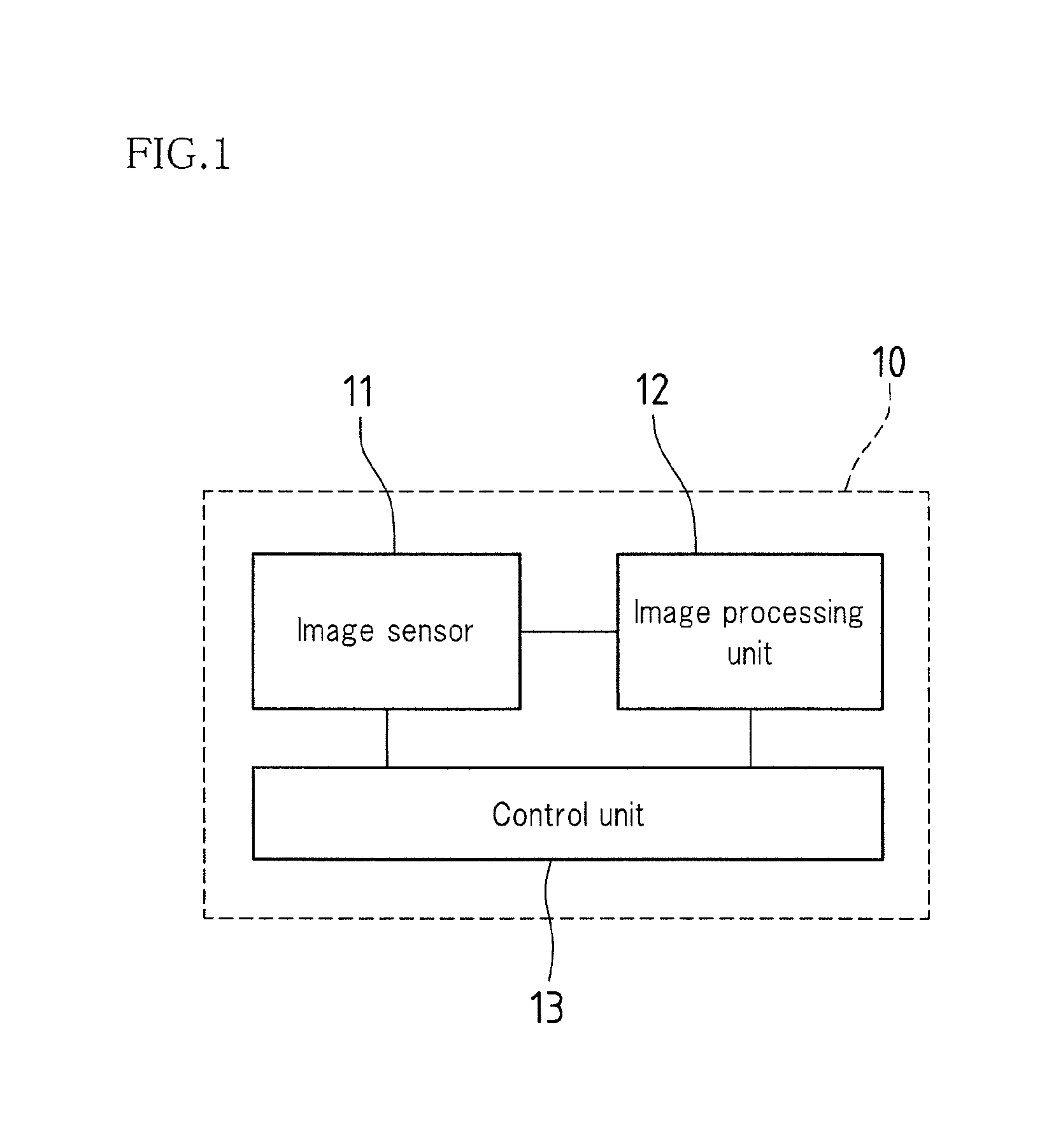
[0040]FIG. 1 is a block diagram showing a schematic configuration of a range image camera 10 according to an embodiment of the present invention.

[0041]As shown in FIG. 1, the range image camera 10 is provided with an image sensor 11 (e.g., TOF sensor) capable of generating a range image after acquiring range data for pixel values based on the time taken for light projected toward a target space to be reflected back, an image processing unit 12 that performs plane estimation (detailed below) of planes in this range image, and a control unit 13 (e.g., CPU) that performs overall control of the range image camera 10.

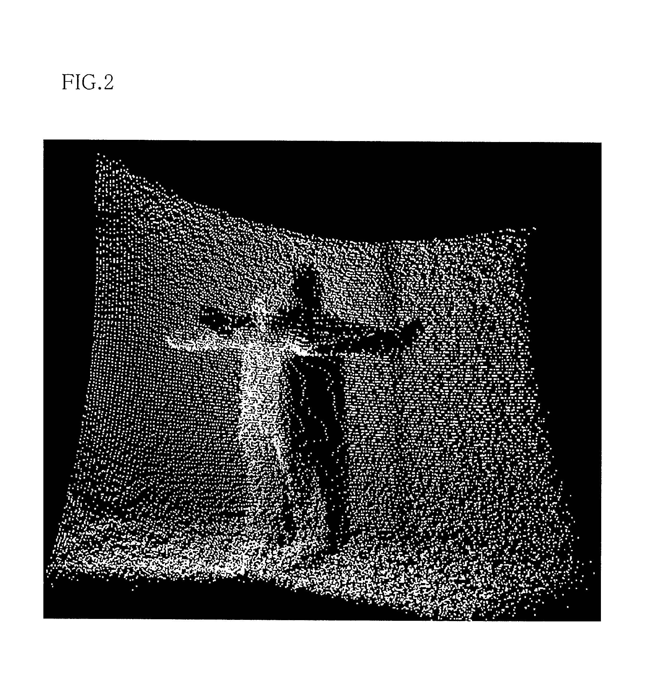
[0042]FIG. 2 shows an example of a range image displayed as 3D information in the case where a human body standing in front of a wall with arms open has been captured by this range image camera 10.

[0043]For example, in an image formed by visible light captured with a norm...


PUM


Abstract

3D data of pixels arranged in a square lattice is converted to a houndstooth arrangement, a largest value among respective magnitudes of cross products of all pairings of the normal vector of a small triangle of interest and the normal vectors of three adjacent small triangles is derived, and a large triangle composed of the small triangle of interest and the adjacent small triangles is determined to be a plane candidate if the largest value is less than or equal to a first threshold, after which similar processing is repeated with this large triangle taken as a small triangle, and this repetition is recursively performed while enlarging the small triangle of interest, and when the area of a new large triangle is greater than or equal to a predetermined area, the region thereof is determined to be a plane and separated from a range image.

Description

CROSS-REFERENCE TO RELATED APPLICATION[0001]This application claims priority under 35 U.S.C. §119(a) on Patent Application No. 2010-050906 filed in Japan on Mar. 8, 2010, the entire contents of which are herein incorporated by reference.BACKGROUND OF THE INVENTION[0002]1. Field of the Invention[0003]The present invention relates to a method for estimating a plane in a captured range image and to a range image camera, and more particularly to a method for estimating a plane in a captured range image by precisely measuring per pixel the time taken for projected light to be reflected back by a target, and to a range image camera to which such a plane estimation method is applied.[0004]2. Related Art[0005]Heretofore, various techniques that involve using a captured image of a target space to perform processing such as monitoring the target space and extracting the appearance of a target object in the target space have been proposed. However, there is a problem in that because the image ...

Claims


Application Information

Patent Timeline
Patent Type & Authority Patents(United States)
IPC IPC(8): H04N13/00G01C3/08H04N5/228
CPCG06T2207/10028G06T7/004G06T2207/20144G06T7/0081G06T7/11G06T7/194G06T7/70
Inventor KAWAHATA, YASUTAKA
Owner OPTEX CO LTD
Why Eureka
Try Eureka