Component crimping apparatus

a crimping apparatus and component technology, applied in mechanical apparatus, instruments, fastening means, etc., can solve problems such as and achieve the effect of preventing failure of component crimping

Active Publication Date: 2017-08-22
PANASONIC INTELLECTUAL PROPERTY MANAGEMENT CO LTD
View PDF10 Cites 2 Cited by
  • Summary
  • Abstract
  • Description
  • Claims
  • Application Information

AI Technical Summary

Benefits of technology

[0009]Hence, an object of the embodiments of the invention is to provide a component crimping apparatus capable of preventing crimping failure from occurring due to previous photocuring of an adhesive member through which a component is not targeted for crimping.
[0011]One of embodiments of the invention can prevent crimping failure from occurring due to previous photocuring of an adhesive member through which a component is not targeted for crimping.

Problems solved by technology

However, in the case of attempting to crimp the components by the plural crimping operations as described above in the component crimping apparatus using the photo-curable adhesive member, light is also applied to an adhesive member of an electrode which is not yet targeted for crimping the component and a region under the electrode in a region of the lower surface of the substrate is not received by the transparent member.
Because of this, the adhesive member may be photocured before crimping the component, and component crimping failure may occur.

Method used


Image

  • Component crimping apparatus
  • Component crimping apparatus
  • Component crimping apparatus

Examples


Embodiment Construction

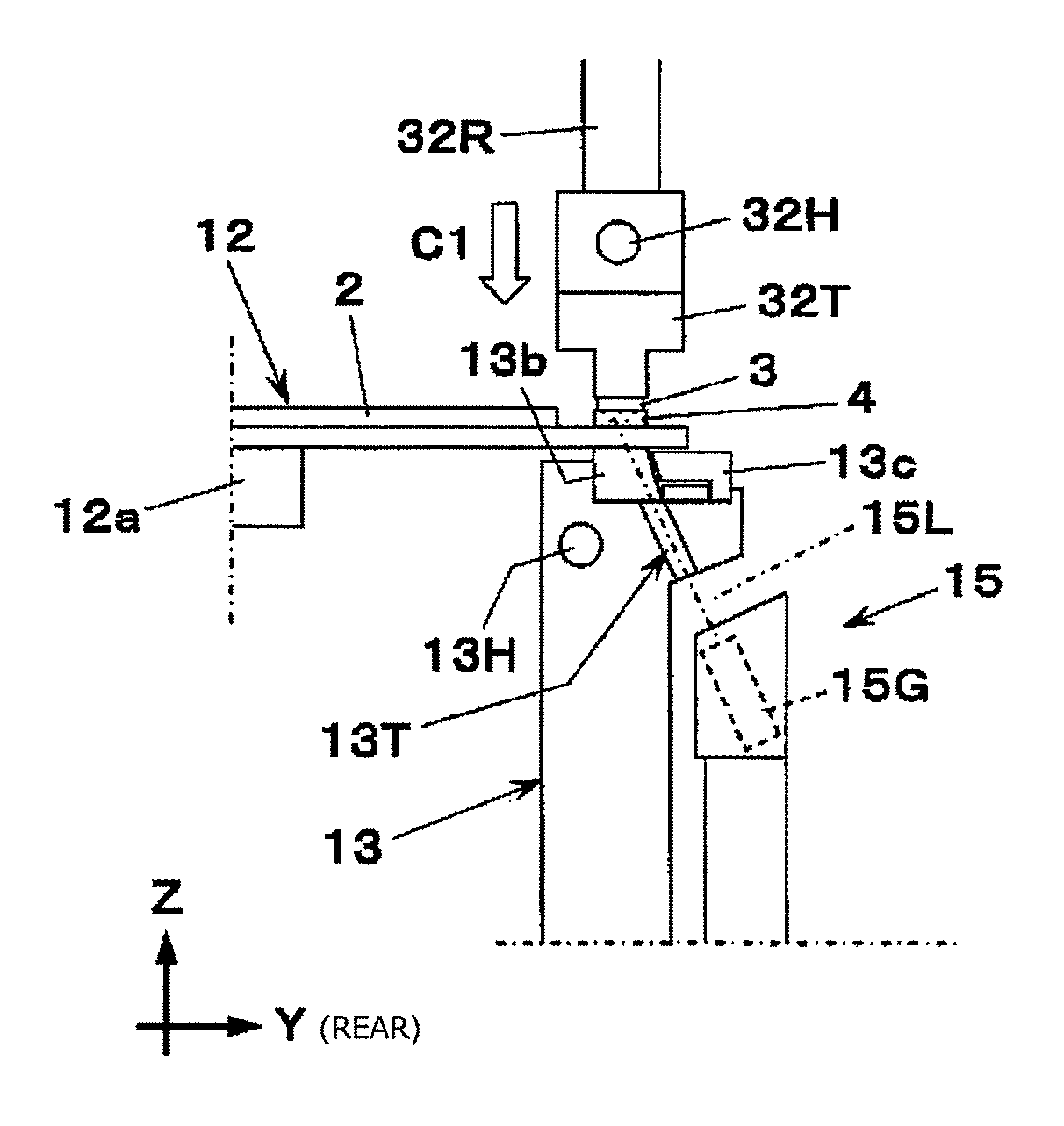
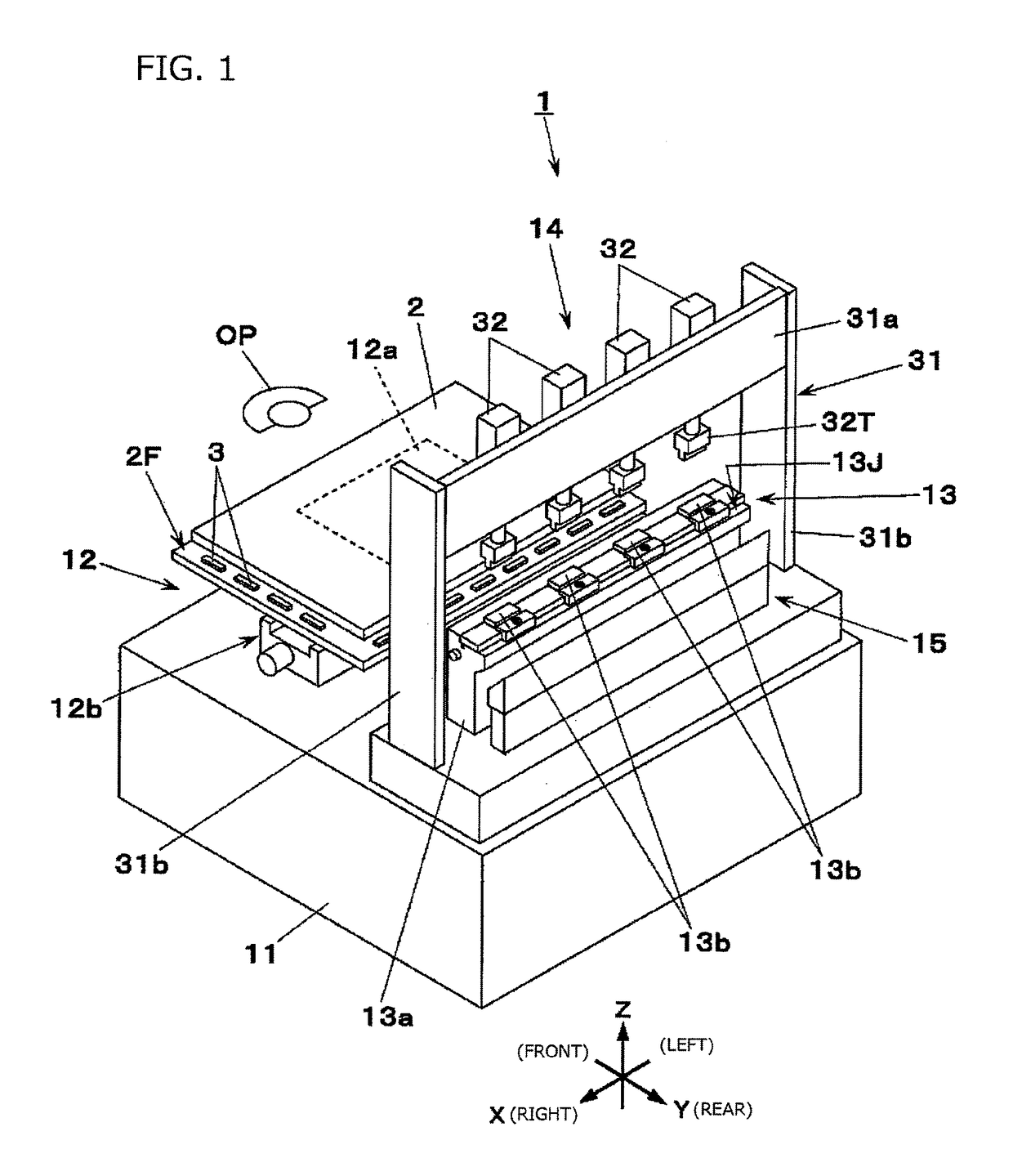
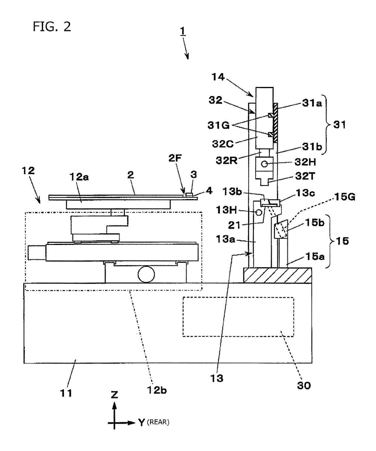
[0023]An embodiment of the invention will hereinafter be described with reference to the drawings. FIGS. 1 to 3 show a component crimping apparatus 1 in the embodiment of the invention. The component crimping apparatus 1 is an apparatus that crimps plural components 3 previously attached (temporarily fixed) to an edge 2F of a substrate 2. The case where the component crimping apparatus 1 is used as a main crimping apparatus in a liquid crystal panel manufacturing system will herein be described by way of example.

[0024]The substrate 2 is made of a transparent material such as glass, and has a generally rectangular shape. Plural electrodes 2d are juxtaposed in each of the two orthogonal edges 2F in four sides included by the substrate 2 (FIG. 4). The component 3 such as an integrated circuit (driver IC) for driving is attached to each of the electrodes 2d through a tape-shaped photo-curable adhesive member 4 to be cured with irradiation with light such as ultraviolet rays. In the pres...


PUM

PropertyMeasurementUnit
transparentaaaaaaaaaa
bonding forceaaaaaaaaaa
temperatureaaaaaaaaaa

Abstract

A component crimping apparatus includes: a substrate holding part that holds a substrate of a transparent material, a component previously attached to each electrode of electrodes juxtaposed in an edge of the substrate through a photo-curable adhesive member; a supporting part having a base part with an optical path and a transparent member on the base part and connected to the optical path, and supports, by the transparent member, a region under a targeted electrode in the substrate; a crimping tool arranged over the transparent member and presses the component to the substrate; a light irradiating part that irradiates the adhesive member attached to the targeted electrode with light through the optical path; and a light shielding member that covers a portion in which the transparent member is not installed in an opening part of the optical path in the base part.

Description

CROSS-REFERENCES TO RELATED APPLICATION(S)[0001]This application is based on and claims priority from Japanese Patent Application No. 2014-167101 filed on Aug. 20, 2014, the entire contents of which are incorporated herein by reference.BACKGROUND[0002]1. Field of the Invention[0003]One or more embodiments of the present invention relate to a component crimping apparatus for bonding a component to each of plural electrodes juxtaposed in an edge of a substrate through an adhesive member.[0004]2. Description of Related Art[0005]A component crimping apparatus is an apparatus for bonding components to plural electrodes formed in an edge of a substrate through adhesive members, and includes a supporting part for supporting a region under the electrode in a region of a lower surface of the substrate, and crimping tools arranged over the supporting part. When the crimping tools press the components on the substrate supported by the supporting part, the components are bonded to the substrate...

Claims


Application Information

Patent Timeline
Patent Type & Authority Patents(United States)
IPC IPC(8): H05K3/32F16B11/00G02F1/13G02F1/1345
CPCF16B11/006H05K3/321H05K3/323G02F1/1303G02F1/13452H05K2203/0195H01L2224/75H01L2224/95
Inventor YAMADA, AKIRATSUJI, SHINJIROADACHI, SATOSHITSUBOI, YASUTAKATSUJIKAWA, TOSHIHIKO
Owner PANASONIC INTELLECTUAL PROPERTY MANAGEMENT CO LTD
Why Eureka
Try Eureka