Torque sensor unit

a technology of torque sensor and torque sensor, which is applied in the direction of instruments, force/torque/work measurement apparatus, transportation and packaging, etc., can solve the problems affecting the detection accuracy of absolute rotation angle, and achieve the effect of accurate determination, excellent positioning ability, and high mounting accuracy of magnets

Inactive Publication Date: 2017-08-22
NTN CORP
View PDF20 Cites 1 Cited by
  • Summary
  • Abstract
  • Description
  • Claims
  • Application Information

AI Technical Summary

Benefits of technology

[0014]If a bearing to which each of the magnetic angle sensors is to be mounted has an inner race and an outer race, it is possible to mount the magnet of the magnetic angle sensor to the inner race so as to rotate together with the inner race, and to mount the magnetic sensor element to the outer race such that its position relative to the outer race remains unchanged. By fixing each magnetic angle sensor to the rolling bearing in this manner, the excellent positioning ability of the rolling bearing itself ensures high mounting accuracy of the magnet and the magnetic sensor element. By supporting the shaft member on the housing through the two rolling bearings, it is possible to fix the two magnetic angle sensors necessary to obtain the difference in output corresponding to the twist angle of the shaft member to the respective rolling bearings. By fixing the inner races of the bearings to the outer peripheral portion of the shaft member, and fitting the outer races of the bearings to the inner peripheral portion of the housing, concentricity of the two rolling bearings is ensured, which in turn ensures, in advance, concentricity of the two magnetic angle sensors fixed to the respective bearings. Since the axial positions of the rolling bearings are restricted by the bearing restricting means, the axial distance between the magnetic angle sensors can be accurately determined in advance. When the shaft member is twisted under torque applied thereto, the inner races, which are fixed to the outer peripheral portion, are rotated corresponding to the degrees of twisting at the respective portions. This causes the corresponding magnets to rotate together with the inner races. The magnetic angle sensors respectively convert the absolute rotation angles of the magnets to output signals. The torque sensor unit is therefore capable of detecting the absolute rotation angles at two locations of the shaft member which indicate the torque-dependent twist angle of the shaft member. In this torque sensor unit, the rolling bearings, the shaft member, the housing, and the bearing restricting means cooperate to ensure accurate mounting of the magnets and the magnetic sensor elements, of the magnetic angle sensors so as to ensure, in advance, accurate positional relationship between the two magnetic angle sensors, and also to allow the torque sensor unit to be handled as an integral unit. Since the shaft member of this torque sensor unit has its both end portions exposed to the outside in the opposite axial directions, the shaft member can be connected at the end portions to the shaft-forming parts of a device so that the shaft member can be used as portions of the shafts of the device. With this arrangement, since it is not necessary to mount, with high accuracy, a magnet and a magnetic sensor element to the shaft and a stationary member, of the device, in addition to a bearing for supporting the shaft, this torque sensor unit can be easily mounted to the device.

Problems solved by technology

Since a magnetic angle sensor calculates the angle based on the magnetic flux density as detected by the magnetic sensor element, mounting errors of the magnet and the magnetic sensor element significantly influence the detection accuracy of the absolute rotation angle.

Method used


Image

  • Torque sensor unit
  • Torque sensor unit
  • Torque sensor unit

Examples


examples

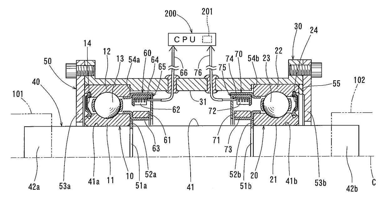
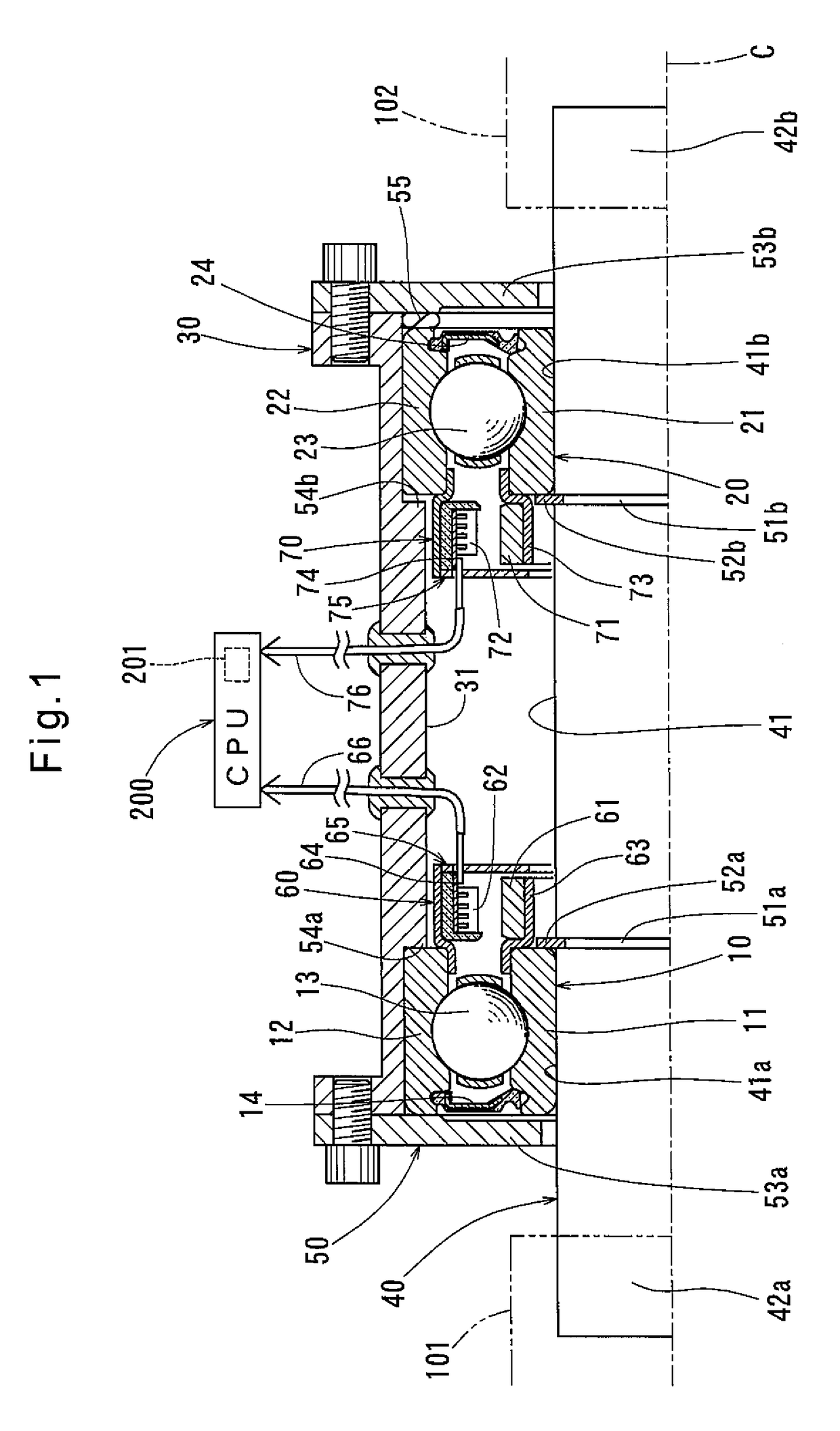
[0025]Now a torque sensor unit as a first specific example is described with reference to FIG. 1. As shown, this torque sensor unit includes a first rolling bearing 10, a second rolling bearing 20, a housing 30, a shaft member 40, a bearing restricting means 50, a first magnetic angle sensor 60, and a second magnetic angle sensor 70. The magnetic angle sensor 60 is fixed to the rolling bearing 10, while the magnetic angle sensor 70 is fixed to the rolling bearing 20.

[0026]The first rolling bearing 10 includes a first inner race 11, a first outer race 12, and a plurality of rolling elements 13 disposed between the inner race 11 and the outer race 12. The second rolling bearing 20 includes a second inner race 21, a second outer race 22, and a plurality of rolling elements 23 disposed between the inner race 21 and the outer race 22. The rolling bearings 10 and 20 themselves have the ability of position the inner and outer races 11 and 12, and the inner and outer races 21 and 22, respec...


PUM

PropertyMeasurementUnit
absolute rotation angleaaaaaaaaaa
magnetic angleaaaaaaaaaa
densityaaaaaaaaaa

Abstract

A torque sensor unit includes two magnetic angle sensors capable of detecting absolute rotation angles of a shaft member which indicate a twist angle of the shaft member when the shaft member is twisted. The shaft member has two end portions exposed to outside so that the shaft member can be connected at the two end portions to shaft-forming parts of a device.

Description

TECHNICAL FIELD[0001]The present invention relates to a torque sensor unit used to measure torque applied to a shaft.BACKGROUND ART[0002]Known contact type torque sensors are used e.g., for vehicle steering devices (as disclosed in the below-identified Patent document 1). A non-contact type torque sensor is known which include two magnetic angle sensors arranged coaxial with a shaft and capable of detecting absolute rotation angles. These angle sensors convert the absolute rotation angles, which correspond to the rotational displacement at the respective axial positions, to output signals. When the shaft is twisted under torque applied to the shaft, the shaft is rotationally displaced about its axis to different degrees at two axially separate points. Thus, by detecting the rotational displacements at the two axially separate points as absolute rotation angles, the twist angle between these two axially separate points is given as the difference in output between such absolute rotati...

Claims


Application Information

Patent Timeline
Patent Type & Authority Patents(United States)
IPC IPC(8): G01L3/00F16C41/00B62D6/10B62D15/02G01L5/22G01L3/10
CPCG01L3/104B62D6/10B62D15/0215F16C41/007G01L5/221F16C19/06F16C19/54F16C2370/00
Inventor ITOMI, SHOJI
Owner NTN CORP
Why Eureka
Try Eureka