Push-pull flipped-die half-bridge magnetoresistive switch

a magnetoresistive switch and push-pull technology, applied in the field of magnetoresistive sensor devices, can solve the problems of low operating frequency and achieve the effects of low operating frequency, high frequency response and small siz

Active Publication Date: 2017-08-22
MULTIDIMENSION TECH CO LTD
View PDF10 Cites 2 Cited by
  • Summary
  • Abstract
  • Description
  • Claims
  • Application Information

AI Technical Summary

Benefits of technology

[0006]Existing switch sensors have a low power sleep state and a high power work state, resulting in low operating frequency. For this purpose, the sensor requires a high-sensitivity in the low-power sleep and working states, low current consumption in both sleep and work states, along with high frequency response, and small size. The present invention provides a push-pull half-bridge magnetoresistive switch, with improved performance over the existing technology.
[0023]According to the preferred implementation of the present invention the beneficial effects are: the half-bridge push-pull structure can improve the sensitivity of the sensor; two sensor chips can be well-matched, to reduce the variation in output voltage and also to reducing the voltage drift with temperature; innovative packaging and wire bonding of the sensor chips reduces the size and improves the performance of the switch sensor.

Problems solved by technology

Existing switch sensors have a low power sleep state and a high power work state, resulting in low operating frequency.

Method used


Image

  • Push-pull flipped-die half-bridge magnetoresistive switch
  • Push-pull flipped-die half-bridge magnetoresistive switch
  • Push-pull flipped-die half-bridge magnetoresistive switch

Examples


embodiment 2

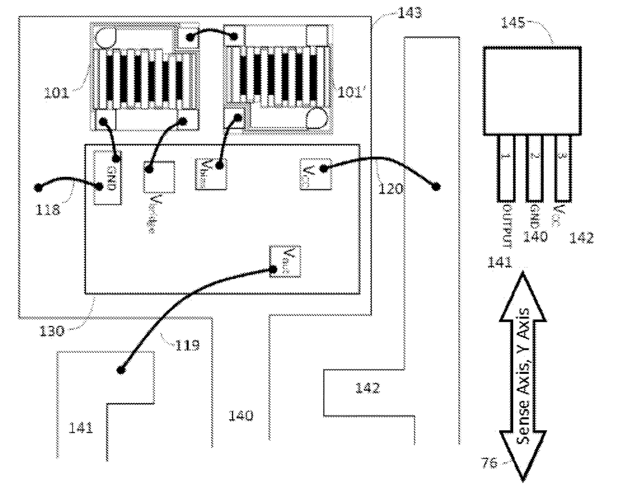
[0058]FIG. 9 is a rectangular chip magnetic sensor chip 101, having the physical layout of embodiment 2 according to the present invention. The chip has four pads 103-106, for providing electrical connections according to the implementation. For example, the pad 104, the corresponding terminal 1.2, has a circular shape, while the other three pads are square. Permanent magnet 71 provides cross-axis bias field Hbias. The magnetoresistor 108 comprises serially connected MTJ elements40. The top electrode 42 is used to achieve electrical connection between the pad and the magnetoresistive element string, between the individual magnetoresistive elements, and between the magnetoresistor strings.

embodiment 3

[0059]FIG. 10 is a rectangular chip magnetic sensor chip 101, having the physical layout of the embodiment 3 according to the present invention. The chip has four pads 103-106, electrical connections according to the present implementation. For example, the pad 104, the corresponding terminal 1.2, a circular shape, while the other three pads are square. Permanent magnet 71 provides cross-axis bias field Hbias. The magnetoresistor 108 comprises a number of serially connected MTJ elements 40. The top electrode 42 is used to achieve electrical connection between the pad and the magnetoresistive element string, between the individual magnetoresistive elements, and between the magnetoresistor strings.

embodiment 4

[0060]FIG. 11 is a rectangular chip magnetic sensor chip 101, having the physical layout of the embodiment 4 according to the present invention. The chip has four pads 103-106, electrical connections according to the present implementation. For example, the pad 104, the corresponding terminal 1.2, a circular shape, while the other three pads are square. Permanent magnet 71 provides cross-axis bias field Hbias. The magnetoresistor 108 comprises a number of serially connected MTJ elements 40. The top electrode 42 is used to achieve electrical connection between the pad and the magnetoresistive element string, between the individual magnetoresistive elements, and between the magnetoresistor strings.

[0061]FIG. 12 is a rectangular chip magnetic sensor chip 101, having the physical layout of the embodiment 5 according to the present invention. The chip 101 has two pads, with respect to each of the above embodiments, each of the chip pads in Example 5 in this embodiment is elongated to acc...


PUM


Abstract

Push-pull half-bridge magnetoresistive switch, comprising two magnetic sensor chips, each magnetic sensor chip having a magnetic induction resistor and a magnetic induction resistor electrical connection pad. The two magnetic sensor chips are electrically interconnected and have opposite and parallel directions of induction, thus forming the push-pull half-bridge circuit. The magnetic induction resistor comprises one or a plurality of magnetoresistive elements connected in series. The magnetic induction resistor pads are located at adjacent edges of the magnetic sensor chips, and each pad may accommodate the welding of at least two bonding wires. The magnetoresistive switch may improve the sensitivity of a sensor, and decrease output voltage deviation and output voltage temperature drift, which is beneficial for decreasing the volume and increasing the performance of the switch sensor.

Description

PRIORITY CLAIM TO RELATED APPLICATIONS[0001]This application is a U.S. national stage application filed under 35 U.S.C. §371 from International Application Serial No. PCT / CN2014 / 074574, which was filed 1 Apr. 2014, and published as WO2014 / 161482 on 9 Oct. 2014, and which claims priority to Chinese Application No. 201310111100.7, filed 1 Apr. 2013, which applications and publication are incorporated by reference as if reproduced herein and made a part hereof in their entirety, and the benefit of priority of each of which is claimed herein.TECHNICAL FIELD[0002]The present invention relates magnetoresistive sensor devices containing multiple chips in a single package. More particularly, the present invention relates to a push-pull flipped-die half-bridge magnetoresistive switch.BACKGROUND TECHNOLOGY[0003]Magnetic switch sensors are widely used in various applications, including consumer electronics, white goods, three common types of utility meters (electricity, water, gas), automotive...

Claims


Application Information

Patent Timeline
Patent Type & Authority Patents(United States)
IPC IPC(8): H03B1/00H03K17/95G01R33/09H03K3/00H03K17/97
CPCG01R33/098G01R33/093H03K17/9517H03K17/97
Inventor BAI, JIANMINSHEN, WEIFENGLEI, XIAOFENGZHANG, XIAOJUNZHONG, XIAOJUN
Owner MULTIDIMENSION TECH CO LTD
Why Eureka
Try Eureka