
Method for controlling a plasma chamber

a plasma chamber and control method technology, applied in the direction of chemical vapor deposition coating, semiconductor/solid-state device testing/measurement, coating, etc., can solve the problems of slow methods, damage to other surfaces inside the chamber, damage to the surface of the material being processed

Active Publication Date: 2017-08-29
ASM AMERICA INC
View PDF28 Cites 31 Cited by
  • Summary
  • Abstract
  • Description
  • Claims
  • Application Information

AI Technical Summary

Benefits of technology

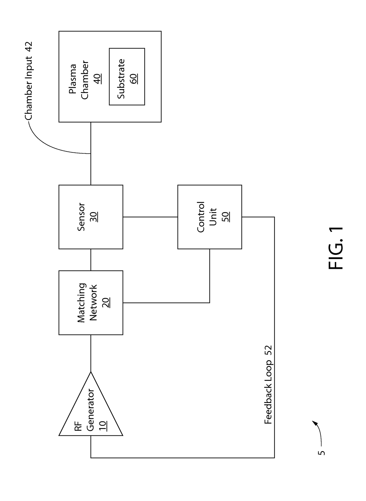
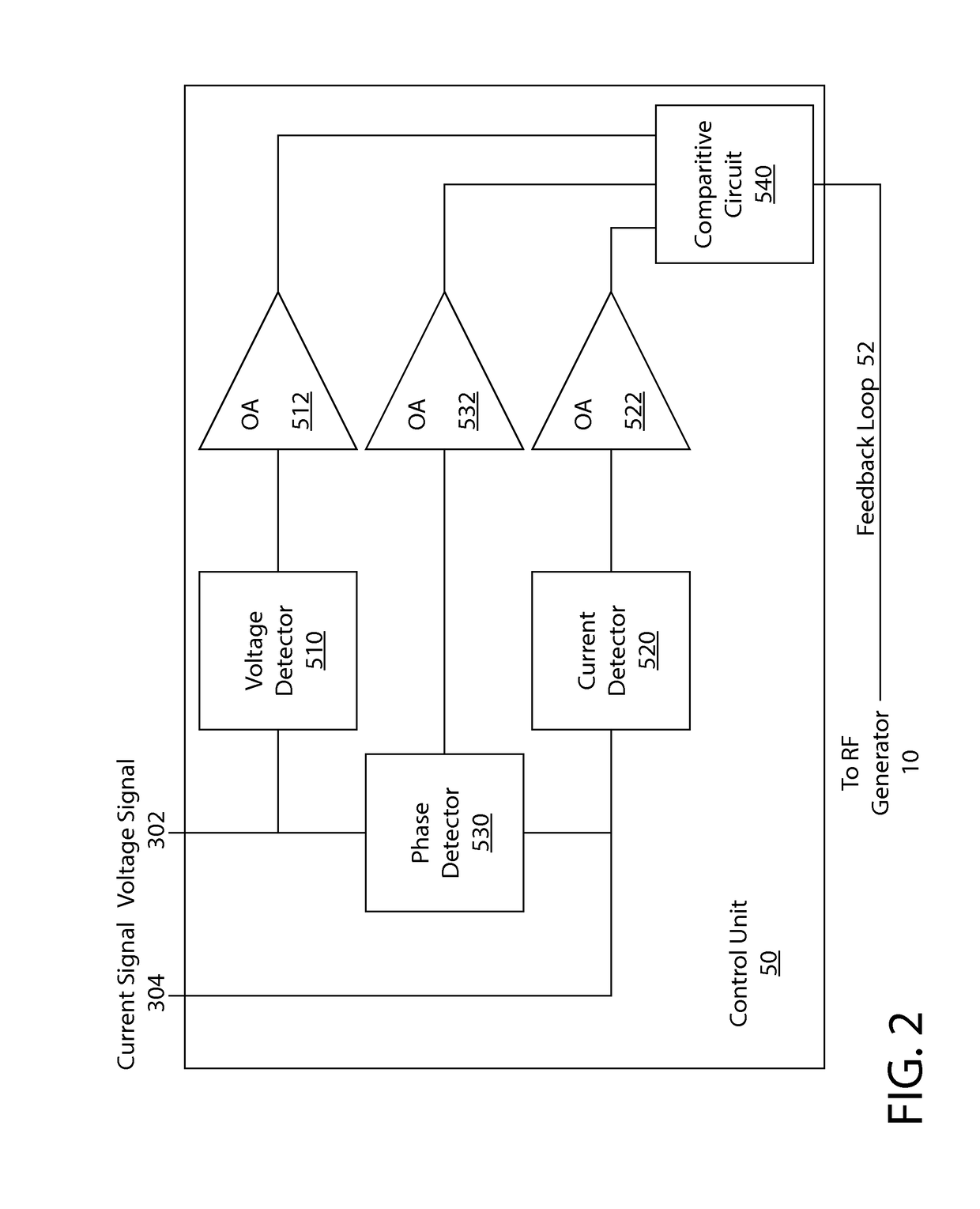
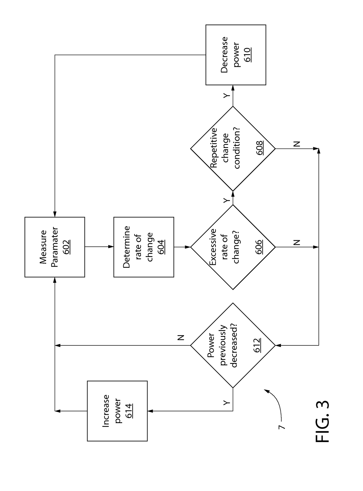
This patent describes a system for controlling a plasma chamber by measuring parameters at the chamber input and detecting abnormal changes in the measured parameters, such as excessive rate of change or repetitive change. When a repetitive change is detected, the system decreases the power of the RF signal provided to the chamber input to prevent damage to the substrate. The technical effect is to improve the quality and efficiency of plasma-related processes such as deposition or etching.

Problems solved by technology

The electrical arc can result in damage to the surface of the material being processed or even cause damage to other surfaces inside the chamber.
Methods have been employed to detect arcing and to either preventing arcing from occurring in the first place or to limit the damage caused by arcing, but these methods are slow and often fail to capture fast transients.

Method used


Image

  • Method for controlling a plasma chamber
  • Method for controlling a plasma chamber
  • Method for controlling a plasma chamber

Examples


Embodiment Construction

[0017]The description of illustrative embodiments according to principles of the present invention is intended to be read in connection with the accompanying drawings, which are to be considered part of the entire written description. In the description of embodiments of the invention disclosed herein, where circuits are shown and described, one of skill in the art will recognize that for the sake of clarity, not all desirable or useful peripheral circuits and / or components are shown in the figures or described in the description. Moreover, the features and benefits of the invention are illustrated by reference to the disclosed embodiments. Accordingly, the invention expressly should not be limited to such disclosed embodiments illustrating some possible non-limiting combinations of features that may exist alone or in other combinations of features; the scope of the invention being defined by the claims appended hereto.

[0018]As used throughout, ranges are used as shorthand for descr...


PUM

PropertyMeasurementUnit
radio frequencyaaaaaaaaaa
voltageaaaaaaaaaa
voltageaaaaaaaaaa

Abstract

An system and method for controlling a plasma chamber includes operably coupling an RF generator to the plasma chamber, the RF generator providing an RF signal to a chamber input of the plasma chamber; measuring a parameter at the chamber input; determining a rate of change based on the measured parameter; detecting an excessive rate of change condition comprising the rate of change exceeding a reference rate of change; detecting a repetitive change condition comprising a predetermined number of the excessive rate of change conditions in a predetermined time; upon detection of the repetitive change condition, decreasing a power of the RF signal provided to the chamber input.

Description

CROSS REFERENCE TO RELATED APPLICATIONS[0001]The present application claims priority to U.S. Provisional Patent Application Ser. No. 61 / 987,725, filed May 2, 2014, the disclosure of which is incorporated herein by reference in its entirety.FIELD OF THE INVENTION[0002]The field of the present invention relates to systems and methods for controlling a plasma chamber, including systems for controlling a plasma chamber used in semiconductor manufacturing.BACKGROUND OF THE INVENTION[0003]The semiconductor device fabrication process uses plasma processing at different stages to make semiconductor devices. Plasma processing involves energizing a gas mixture by imparting energy to the gas molecules by introducing radio frequency (RF) energy into the gas mixture. This gas mixture is typically contained in a vacuum plasma chamber, and the RF energy is typically introduced into the plasma chamber through electrodes.[0004]In a typical plasma process, the RF generator generates power at a radio ...

Claims


Application Information

Patent Timeline
Patent Type & Authority Patents(United States)
IPC IPC(8): C23C16/52C23C16/505H01L21/66H01J37/32
CPCC23C16/505C23C16/52H01J37/32082H01J37/3299H01J37/32935H01L22/26
Inventor BHUTTA, IMRAN AHMED
Owner ASM AMERICA INC
Learn More