Bale opener

a technology of ball screw drive and ball screw, which is applied in the field of ball screw drive, can solve the problems of more than 500 kg of total weight of the stripping arm, and achieve the effect of reducing the frictional force inside the ball screw driv

Active Publication Date: 2017-08-29
MASCHINENFABRIK RIETER AG
View PDF67 Cites 1 Cited by
  • Summary
  • Abstract
  • Description
  • Claims
  • Application Information

AI Technical Summary

Benefits of technology

[0018]It is particularly advantageous if the fastening of the lifting spindle via a load cell on the stripping tower is provided only at an upper end of the lifting spindle and the lifting spindle is not held in the stripping tower or guided there at its lower end. Due to this type of fastening of the lifting spindle, which is equivalent to being suspended, this yields a further reduction in the frictional forces inside the ball screw drive. Clamping of the lifting spindle by means of an upper and lower fastening can lead to imprecise movements of the ball nut because of temperature differences or stresses that occur within the lifting spindle.

Problems solved by technology

Stripping arms contain the stripping element, which is usually one or more stripping rollers with the respective drive units, which result in a total weight of the stripping arm of more than 500 kg, even with smaller systems.

Method used


Image

  • Bale opener
  • Bale opener
  • Bale opener

Examples


first embodiment

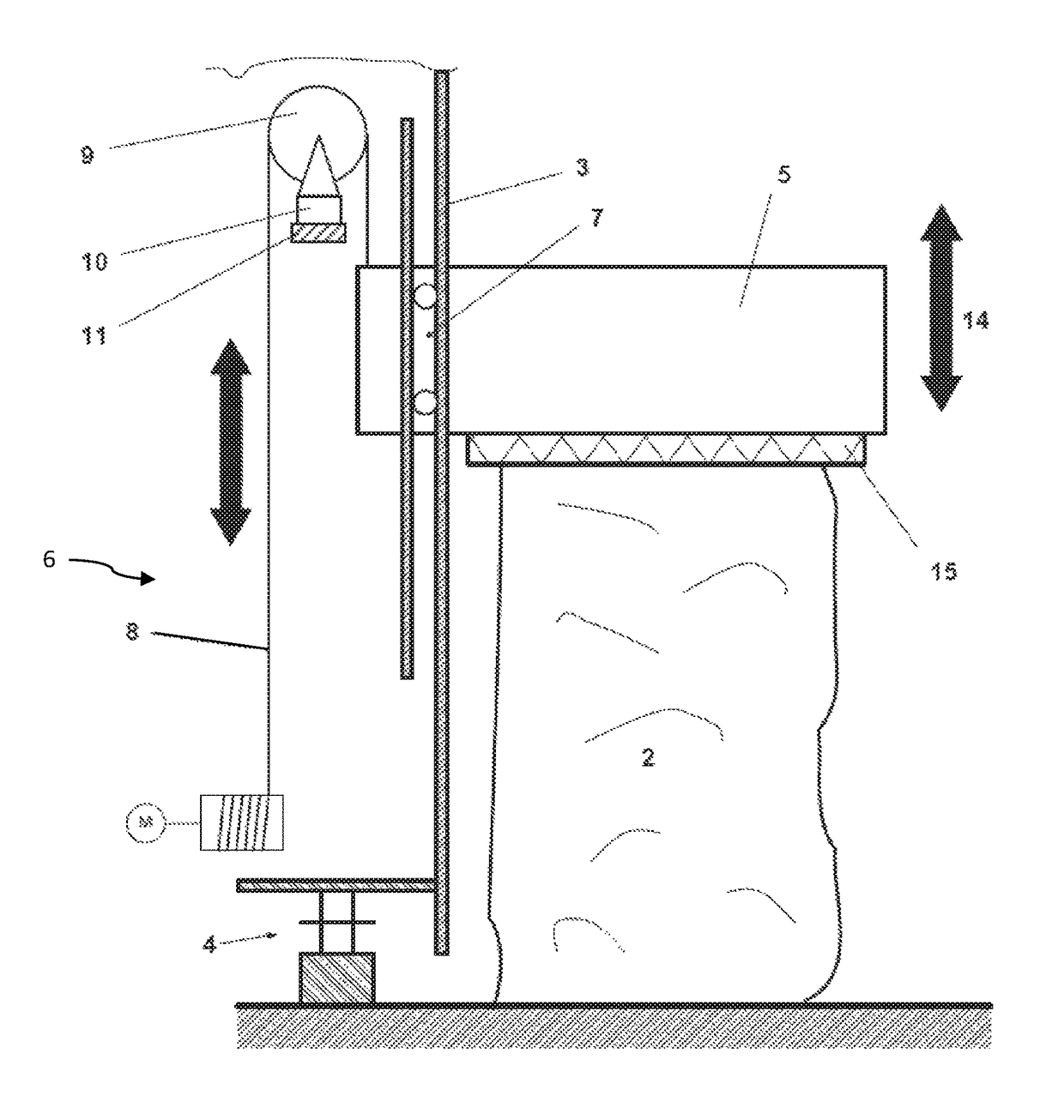
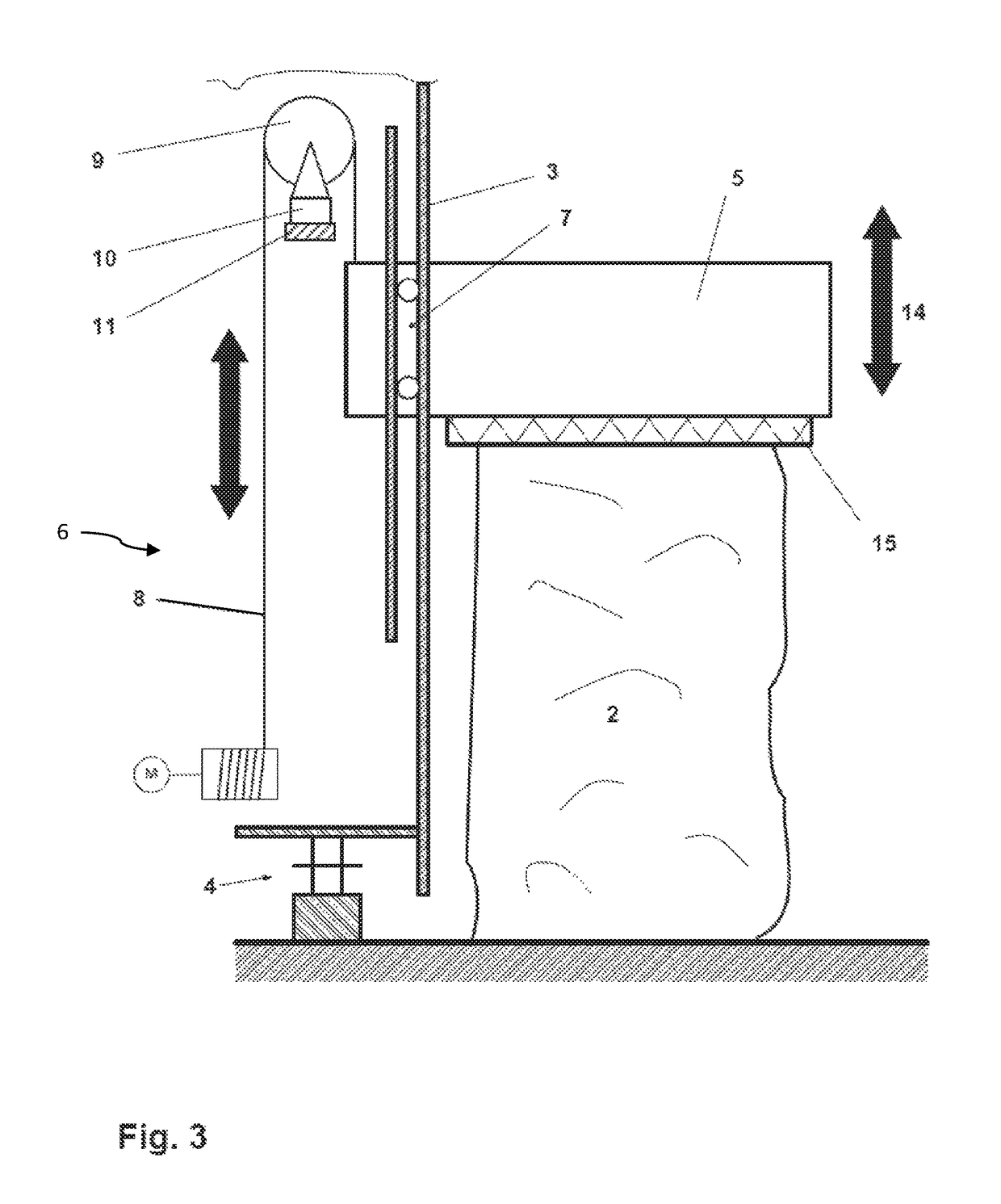
[0028]FIG. 3 shows a schematic view of a first embodiment in a sectional diagram A-A according to FIG. 2. On the basis of FIG. 3, the principle of the weight measurement or force measurement will be demonstrated. The diagram of the individual components as well as their arrangement is given as an example. The stripping arm 5 rests on the fiber bale 2 together with the stripping element 15 in the diagram shown here and is therefore in the stripping position. The stripping tower 3 is shown only in part and is standing on a running gear 4, with the help of which it is guided past the fiber bale 2. The stripping tower 5 is mounted so that it is cantilevered freely in a height-adjustable mount over a guide 7 in the stripping tower 3. The guide 7 is designed so that the stripping arm 5 can execute a vertical movement 14.

[0029]The lifting gear 6 for the movement 14 of the stripping arm 5 is designed as a chain drive. A chain 8, which is guided over a chain wheel 9 to the chain drive is sec...

second embodiment

[0030]FIG. 4 shows a schematic view of a second embodiment in a sectional diagram A-A according to FIG. 2. The stripping arm 5 together with the stripping element 15 rests on the fiber bale 2 in the diagram shown here and is thus in the stripping position. The stripping tower 3 is shown only in part and rests on a running gear 4 with the help of which it is guided past the fiber bale 2. The stripping arm 5 is held in a freely cantilevered manner on the stripping tower 3 by means of the guide 7. The guide 7 is designed so that the stripping arm 5 can execute a vertical movement 14.

[0031]The lifting spindle 18, which is surrounded by a ball nut 19, passes through the stripping arm 5. The ball nut 19 together with its housing is held in a fixed position in the mount 12 on the stripping arm 5. The ball nut 19 is connected to a drive mounted in the stripping arm 5. The drive induces rotation of the ball nut 19 which leads to a lifting or lowering of the stripping arm 5, depending on the ...


PUM

PropertyMeasurementUnit
total weightaaaaaaaaaa
heightaaaaaaaaaa
forceaaaaaaaaaa

Abstract

A bale opener for stripping fiber flocks from fiber bales, including a stripping tower arranged on a running gear or a bogie and having a stripping arm. The stripping arm is mounted in a height-adjustable mount in a guide on the stripping tower. A lifting gear is provided for the height adjustment of the stripping arm, wherein the lifting gear is mounted on the stripping arm and on the stripping tower, and the lifting gear has at least one load cell.

Description

FIELD OF THE INVENTION[0001]The invention relates to a bale opener for stripping fiber flocks from fiber bales using a stripping tower arranged on a running gear or a bogie and using a stripping arm.BACKGROUND[0002]Bale stripping machines or bale openers are used to release fibers or fiber flocks from pressed fiber bales. To do so, a stripping element is moved over the fiber bales. The stripping element is mounted on a stripping arm, which is adjusted in height on the present fiber bales. The stripping arm is in turn held on a stripping tower. The stripping tower makes it possible for the stripping element to be movable over the surface of the fiber bales to be stripped. The stripping arm is arranged on a running gear or a bogie. With a running gear, which is usually guided on rails, it is possible to move along a row of bales. If the fiber bales are arranged in a circle around the stripping tower, the stripping tower is arranged on a bogie. A combination of a running gear and a bog...

Claims


Application Information

Patent Timeline
Patent Type & Authority Patents(United States)
IPC IPC(8): A01G7/04D01G7/04D01G7/10D01G7/14
CPCD01G7/04D01G7/10D01G7/14B65B69/00
Inventor SCHMID, ALEXANDERGSCHLIESSER, GERHARD
Owner MASCHINENFABRIK RIETER AG
Why Eureka
Try Eureka