
Building ventilator

a ventilator and building technology, applied in ventilation systems, domestic cooling apparatuses, heating types, etc., can solve the problems of affecting the efficiency of thermal energy transfer, affecting the safety of electronics equipment, and international legislation imposing emission limitations and energy efficiency requirements, so as to achieve maximum thermal energy transfer efficiency

Inactive Publication Date: 2017-08-29
REDRING ELECTRIC
View PDF18 Cites 0 Cited by
  • Summary
  • Abstract
  • Description
  • Claims
  • Application Information

AI Technical Summary

Benefits of technology

[0006]It is an objective of the present invention to provide a ventilator for a building that maximises the efficiency of thermal energy transfer between a flow of air into the building and a flow of air out of the building. It is a further specific objective to provide a ventilator configured to provide moisture management of the air that is exhausted from the building interior to firstly prevent the moisture from being reintroduced into the building interior if desired and to protect the internal components of the ventilator from water damage in addition to providing a mechanism for removing condensation within the ventilator during normal use.
[0007]It is a further specific objective to provide a ventilator that is compact in construction and therefore enables convenient installation at a building and in particular an external building wall or external region of a building to provide a conduit for the flow of fresh air from an external region of the building and the exhaust of warm, stale and / or humid air from within the building interior.
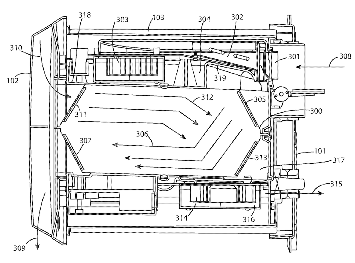
[0008]The objectives are achieved by the present ventilator configured to independently drive two counter-air flow streams (including a first fresh air stream from the external side of the building and a second air flow stream form the building interior) through a single heat exchanger / recuperator mounted internally within the device. Advantageously the building ventilator of the present invention has first and second impellers configured to independently drive two counter-air flow streams (including a first fresh air stream from the external side of the building and a second air flow stream form the building interior) through a single heat exchanger / recuperator mounted internally within the device. Advantageously, one impeller is positioned in the air flow stream between the heat exchanger and an air flow outlet port provided at an external region of the building to optimise the exhaust flow of air from the building interior via the ventilator. The air flow characteristics of the exhaust air flow through the ventilator are accordingly optimised to maximise heat recovery and in particular the transfer of heat energy to the fresh air flow stream. Positioning one of the impellers in the air flow path immediately downstream of the heat exchanger and immediately upstream of the external outlet port (with respect to the flow of extracted air) is beneficial to draw into the ventilator the stale air from within the building interior and then to drive this air (after it has transferred its thermal energy to the counter flow fresh air flow stream) out of the ventilator where it is exhausted to the environment.
[0009]This relative positioning of the impeller at the exhaust air flow outlet is also advantageous to control and manage moisture / condensation within the ventilator and in particular the building interior. The impeller location within the ventilator relative to the heat exchanger and the exhaust outlet port is effective to entrain condensation or moisture within the ventilator exhaust air flow stream and to eject, and in particular force, the condensation directly from the exhaust outlet port in the form of vapour, water droplets, mist etc. The present device is also further advantageous by including one or more liquid collection reservoirs, directing channels (or fluid conduits) such that condensation within the ventilator at various internal regions is collected and transferred to the exhaust impeller and efficiently ejected directly through the exhaust outlet port at the external region of the building.
[0016]Preferably, the trough is provided in fluid communication with the well via a U-bend tube. Such an arrangement is advantageous to provide and maintain the partitioning of the internal regions of the cavity that mounts the heat exchanger and in particular the zones of the internal cavity in communication with the external inlet and outlet ports and the zones of the cavity in communication with the internal inlet and outlet ports.

Problems solved by technology

In addition, most ventilation systems act to regulate the internal temperature of the building where occupants, equipment and solar heat increase the building's internal temperature which if unregulated becomes uncomfortable and can be harmful to electronics equipment for example.
In response to climate change and in particular global warming, international legislation has imposed emission limitations and energy efficiency requirements.

Method used


Image

  • Building ventilator
  • Building ventilator
  • Building ventilator

Examples


Embodiment Construction

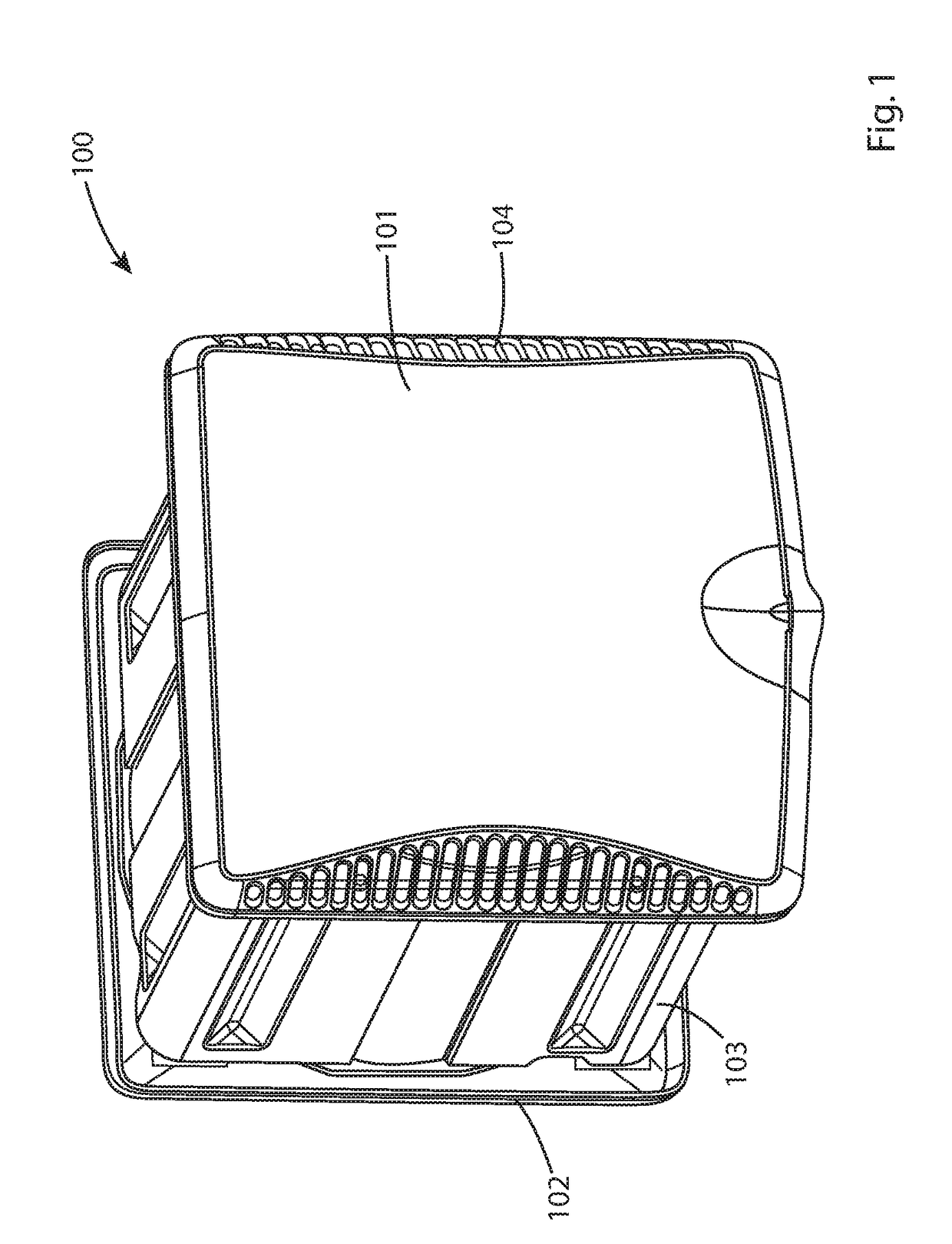
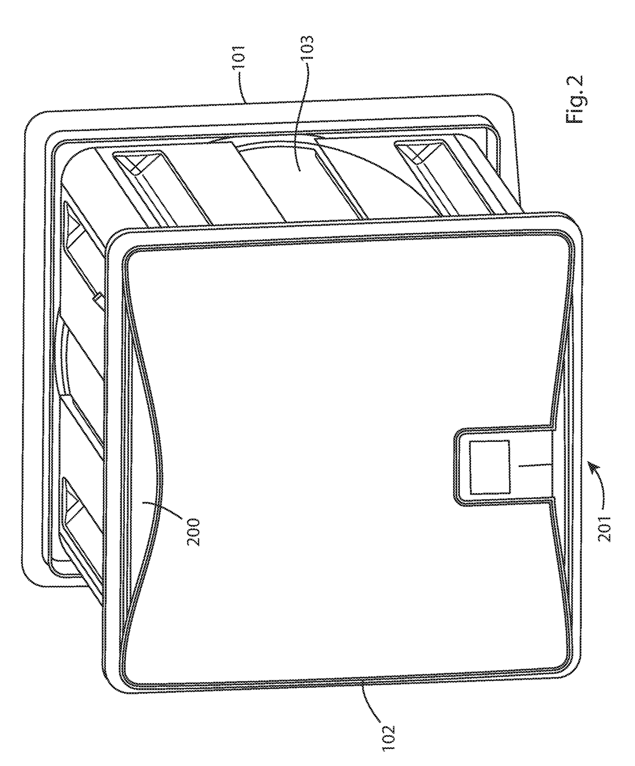
[0032]Referring to FIGS. 1 and 2, a building ventilator 100 comprises an external cover plate 101 for positioning at an external region of a building and an internal cover plate 102 for mounting at the building interior. A main body 103 extends between the external and internal plates 101, 102 such that body 103 and plates 101, 102 collectively define a housing mountable at an aperture in a building wall. Ventilator 100 is configured to allow a first air flow stream to flow from an external region of the building to the building interior in addition to a second counter air flow stream from the building interior to the building exterior. External plate 101 comprises a plurality of vent apertures 104 to allow the supply flow of air from the building external environment into the ventilator 100 and the building interior in addition to providing the exhaust of the extraction flow of air from the building interior to exterior. Cover plate 101 is removably secured to main body 103 via one...


PUM


Abstract

A building ventilator to provide a supply of air into a building comprises an external inlet port and a separate external outlet port and an internal inlet port and a separate internal outlet port to allow respective airstreams to flow into and out of the ventilator respectively at an exterior and at an interior of the building; a heat exchanger mounted in the flow paths between the external and internal inlet and outlet ports. The ventilator is configured to drive an airflow from the external inlet port through the heat exchanger and out of the ventilator via the internal outlet port; and to drive an airflow from the internal inlet port through the heat exchanger and out of the ventilator via the external outlet port. The ventilator comprises a heating element mounted in the air flow path between the external inlet port and the heat exchanger.

Description

CROSS-REFERENCE TO RELATED APPLICATION(S)[0001]This application claims the priority benefit of British Patent Application No 1504311.0 filed Mar. 13, 2015 in the United Kingdom, the entire content of which is incorporated herein by reference.FIELD OF INVENTION[0002]The present invention relates to a building ventilator configured to transfer heat energy between a flow of air exhausted from an interior of a building and a flow of fresh air supplied into the interior of the building.BACKGROUND ART[0003]Most modern buildings require a ventilator system to provide a supply of fresh air into the building interior. In addition, most ventilation systems act to regulate the internal temperature of the building where occupants, equipment and solar heat increase the building's internal temperature which if unregulated becomes uncomfortable and can be harmful to electronics equipment for example.[0004]Most territories have regulations that establish minimum fresh air requirements for the build...

Claims


Application Information

Patent Timeline
Patent Type & Authority Patents(United States)
IPC IPC(8): F24H3/06F24F13/30F24F13/14F25D21/06F24F7/08F24F12/00F24F13/22F24F11/00
CPCF24F12/001F24F7/08F24F12/006F24F13/14F24F13/222F24F13/30F25D21/06F24F2011/0087F24F2013/1433F24F2013/227Y02B30/563F24F11/41Y02B30/56F24F7/013
Inventor HOLLAND, JOSEPHSPEARMAN, DON
Owner REDRING ELECTRIC
Learn More