System and method for bidirectional wireless power transfer

a wireless power supply and wireless technology, applied in the direction of electric variable regulation, process and machine control, instruments, etc., can solve the problems of affecting the operation and the interface of the conventional connector is prone to mechanical failure, so as to reduce or eliminate the power draw of the wireless power supply. , the effect of simple and effectiv

Active Publication Date: 2017-08-29
PHILIPS IP VENTURES BV
View PDF33 Cites 19 Cited by
  • Summary
  • Abstract
  • Description
  • Claims
  • Application Information

AI Technical Summary

Benefits of technology

[0013]In one embodiment, the remote device may include a two-quadrant power supply capable of operating in a boost mode in the transmit mode and operating in a buck mode in the receive mode. For example, in the transmit mode, the two-quadrant power supply may boost the voltage of the remote device's battery to levels sufficient for efficient power transmission. And in receive mode, the two-quadrant power supply may reduce the rectified voltage output from the wireless power transceiver circuitry to a level appropriate for charging the battery of the remote device or powering the load of the remote device.
[0016]In one aspect, the present invention provides a simple and effective system for reducing or eliminating power draw in a wireless power supply while it remains idle. For example, if the wireless power supply is in an environment in which it spends a large amount of time in standby, such as in an office area or the home, power draw during this standby time may be reduced or eliminated. In another aspect, the present invention may provide an effective system for a remote device to alternately transmit or receive power. For example, the remote device may receive power in some circumstances without a controller or without sufficient power to initially operate a controller.

Problems solved by technology

However, these conventional connector interfaces suffer from a variety of drawbacks.
The connector interface in some instances is a proprietary interface, which can become a barrier to interoperability with other remote devices.
Connector interfaces also may leave electrical contacts exposed so that environmental factors, such as exposure to water, can damage the remote device.
And, these interfaces are often prone to mechanical failure.
However, there are some differences: conventional wireless power supplies include drive circuitry to energize the primary whereas conventional remote devices include passive rectification circuitry to condition power received in the secondary.
Unlike cord and connector interfaces, which use wall power, conventional wireless power supplies often remain idle while awaiting a remote device to power.
This constant draw, though small, may amount to a large waste of energy over long periods or when compounded by multiple power supplies being left idle.
There have been solutions to minimize this waste, but none appear to substantially or completely eliminate this waste.

Method used


Image

  • System and method for bidirectional wireless power transfer
  • System and method for bidirectional wireless power transfer
  • System and method for bidirectional wireless power transfer

Examples


second embodiment

D. Second Embodiment

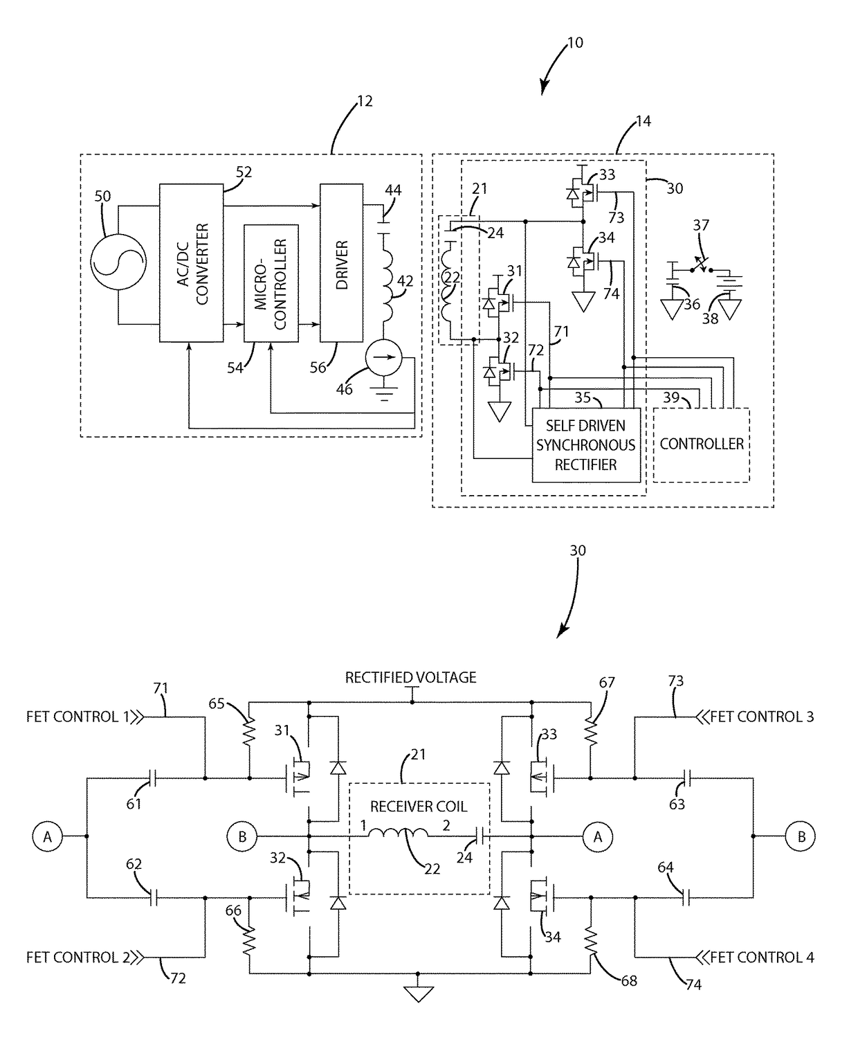
[0110]In a second embodiment of the present invention, the wireless power supply system 110 is similar to those described herein with respect to wireless power supply system 10, including wireless power supply 12 and remote device 14, with several exceptions. The second embodiment may include a remote device 114 similar to the remote device 14 of the illustrated embodiments of FIGS. 1-8 but with multiple secondaries. In one embodiment, multiple secondaries in remote device 114, 114′ may be selectively activated to transmit or receive wireless power. It should be understood that remote devices 114, 114′ are not limited to operation with each other, and that the remote device 114 may be used in conjunction with other devices or wireless power supplies described herein, including wireless power supply 12 as shown in the illustrated embodiment of FIG. 9.

[0111]In the illustrated embodiments of FIGS. 9-13, the remote devices 114, 114′ are similar to the remote device 1...

third embodiment

E. Third Embodiment

[0121]In a third embodiment of the present invention, the wireless power supply system 210 is similar to those described herein, including wireless power supply 12, with several exceptions. The third embodiment may include a wireless power supply 212 similar to the wireless power supply 12 of the illustrated embodiment of FIGS. 1 and 3-7 but with additional circuitry controlling the converter 52.

[0122]The wireless power supply 212 according to this third embodiment is described with respect to the illustrated embodiments of FIGS. 14 and 15. As with the wireless supply 12, the wireless power supply 212 may include a coupler 46 capable of activating the converter 52 in response to power being present in the primary 42. Wireless power supply 212 may further include logic circuitry 251 capable of accepting an input from other sources, enabling activation of the converter 52 or continued activation of the converter 52 from a source other than the coupler 46.

[0123]In th...

fourth embodiment

F. Fourth Embodiment

[0127]In a fourth embodiment of the present invention, the wireless power supply system 310 is similar to those described herein, with several exceptions. The fourth embodiment may include a wireless power supply 312 similar to the wireless power supply 12 and a remote device 314 similar to the remote device 14. As mentioned herein, the wireless power supply 312 and the remote device 314 may include circuitry capable of establishing a separate communication link therebetween, such as an NFC link, TransferJet link, or a Bluetooth link. Such a communication link may be formed by a low power communication system, allowing the remote device 314 to locate wireless power supplies using the same methods it uses to locate other types of devices / sensors without using excess power or draining excess power from the battery. For example, the wireless power supply 312 may include an NFC tag 344 and an NFC tag coil 342, and the remote device 312 may include an NFC transceiver ...


PUM

PropertyMeasurementUnit
rail voltageaaaaaaaaaa
currentaaaaaaaaaa

Abstract

The present invention relates to a wireless power supply system including a remote device capable of both transmitting and receiving power wirelessly. The remote device includes a self-driven synchronous rectifier. The wireless power supply system may also include a wireless power supply configured to enter an OFF state in which no power, or substantially no power, is drawn, and to wake from the OFF state in response to receiving power from a remote device.

Description

BACKGROUND OF THE INVENTION[0001]The present invention relates to wireless power transfer, and more particularly to bidirectional power transfer to and from a remote device.[0002]There has been an ever increasing presence of remote devices in public use. Remote devices such as mobile phones, digital music players, tablets, personal digital assistants, sensors and other similar electronic devices have become nearly ubiquitous in many parts of the world.[0003]As the presence of these types of remote devices increases, their design and feature set changes and advances from one product cycle to the next. In particular, the power interface for charging or powering remote devices has advanced in many respects. Several early remote devices were designed to receive power from a power supply, such as a an AC adapter, via a cord and connector interface. However, these conventional connector interfaces suffer from a variety of drawbacks. The connector interface in some instances is a proprieta...

Claims


Application Information

Patent Timeline
Patent Type & Authority Patents(United States)
IPC IPC(8): H01F38/00H04B5/00H02J5/00H02M3/335H02J7/00H02J7/02
CPCH02J5/005H04B5/0037H04B5/0093H02J7/025H02J2007/0096H02M3/33584Y02B40/90H02J7/00034H02J50/12H02J7/342H02J7/007H02J50/80Y02B40/00
Inventor VAN DEN BRINK, JOSEPH C.TAYLOR, JOSHUA B.NORCONK, MATTHEW J.MOORE, COLIN J.MOES, BENJAMIN C.KUYVENHOVEN, NEIL W.BAARMAN, DAVID W.
Owner PHILIPS IP VENTURES BV
Why Eureka
Try Eureka