Tracking device for portable astrophotography of the night sky

a tracking device and astrophotography technology, applied in the field of astrophotography, can solve the problems of requiring heavy counterweights, requiring a large amount of weight, and limiting exposure to around 10 seconds

Active Publication Date: 2017-08-29
HOLMES ALAN
View PDF12 Cites 10 Cited by
  • Summary
  • Abstract
  • Description
  • Claims
  • Application Information

AI Technical Summary

Problems solved by technology

However, such designs usually have off-axis mounting for the telescope and substantial weight displaced from the centerline of the mounting base, requiring heavy counterweights.
However, the astrophotographer soon discovers that when he or she mounts his camera on a fixed tripod, that the rotation of the sky blurs the images fairly quickly.
The amateur can improve this situation by using shorter focal length, wide angle lenses, but still with any lens other than a fisheye lens exposures are limited to around 10 seconds.
This solution is adequate for very wide angle astrophotography, but disappointing for longer lens used to photograph smaller objects.
This is not true guiding since the process is open loop; that is, no images are captured while the exposure is in progress, resulting in small errors that eventually accumulate and corrupt the image.
This technique works more poorly in the Southern Hemisphere, where Polaris is not visible and there is no comparable bright star.
These work well, but the amateur then confronts another problem.
Most telescope drives, in long exposures, show periodic error in their main worm gear driving the polar axis compensating for the sky, or have some deflection in their structures that result in small errors creeping into the guiding and blurring the images.
Now the problem for the amateur becomes transporting this bulky system to a dark sky site, perhaps a long plane flight away in the Southern Hemisphere, or up a mountain trail to a hilltop.

Method used


Image

  • Tracking device for portable astrophotography of the night sky
  • Tracking device for portable astrophotography of the night sky
  • Tracking device for portable astrophotography of the night sky

Examples


Embodiment Construction

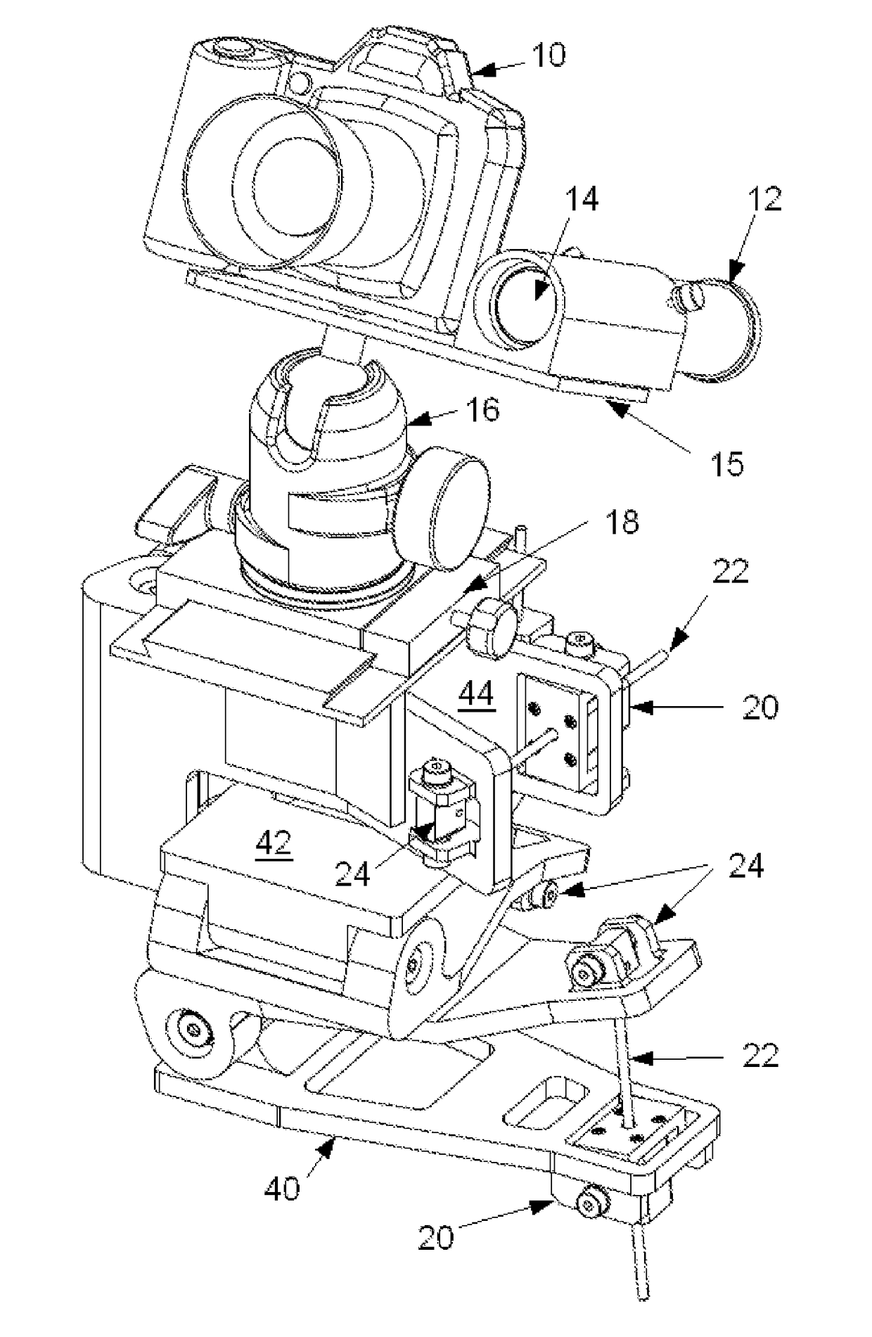
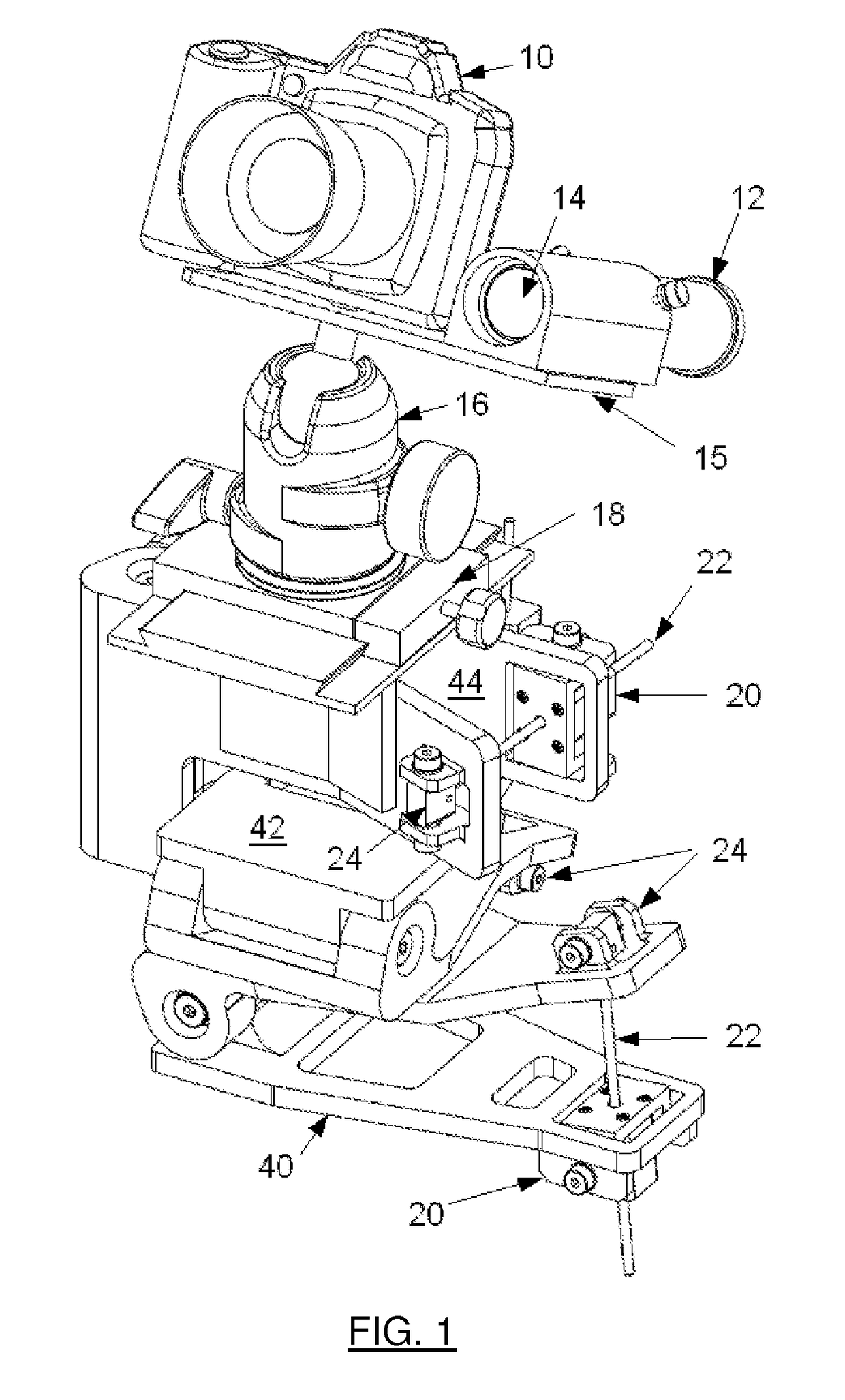
[0019]The present tracking device is illustrated in schematic form in FIG. 1. The device uses at least one tilt stage which can be tilted about three axes. In the exemplary embodiment shown in FIG. 1, three orthogonal tilt stages (40, 42, and 44) are stacked to produce a system whereby a dovetail plate 18, and therefore all the components above it, such as a camera 10, a guider / lens 12 / 14 (referred to herein as a ‘guider camera’), and a camera mounting plate 15 can be tilted in three axes. Here the axes are azimuth (44), elevation (42), and rotation about a horizontal axis (40), but in practice the axes do not need to be lined up with local vertical. The tilt stage for each axis is implemented here using a well-known ‘tangent arm’ design, where linear stepper motors 20 (two of which are visible in FIG. 1) drive each axis separately via respective lead screws 22 to achieve fine step, and therefore angle, resolution. The camera is mounted to the top stage using an adjustable mount, su...


PUM


Abstract

A tracking device for use when performing astrophotography comprises a guider camera and at least one tilt stage, with the topmost of the tilt stages arranged to support an astrophotography camera and the guider camera. Actuators are coupled to the tilt stages such that the astrophotography and guider cameras can be tilted about three axes. The guider camera and actuators are connected to electronics which include a computer programmed to operate in a calibration mode and a tracking mode. In calibration mode, a calibration procedure determines the effect of each actuator on the positions of at least two objects within the field-of-view (FOV) of the guider camera. In tracking mode, the actuators are operated as needed to maintain the positions of the at least two objects constant within the said FOV.

Description

BACKGROUND OF THE INVENTION[0001]Field of the Invention[0002]This invention relates to astrophotography, and more particularly to tracking devices used to enable long exposures when performing astrophotography.[0003]Description of the Related Art[0004]Astronomers have been photographing the night sky for many decades. In the early years of astrophotography film emulsions were not very sensitive, and telescope mountings were designed to allow exposures hours in length while the mount accurately followed the stars. The rotation of the earth is approximately 15 arc-seconds of angle per second of time, and the accuracy of tracking must be on the order of 1 arc-second of angle to not blur the resulting image. Many types of telescope mountings were developed to solve this problem, such as the German Equatorial, or an Equatorial Fork design, for example. Many books and publications describe the various permutations of these designs. A common characteristic of these designs is that they hav...

Claims


Application Information

Patent Timeline
Patent Type & Authority Patents(United States)
IPC IPC(8): H04N5/232G06T7/80G01S3/786H04N5/262G06T7/70G01S5/02G03B17/56G02B23/00F16M11/18G01S3/782G02B23/16
CPCH04N5/23216G01S3/7864G01S5/0278G03B17/561G06T7/70G06T7/80H04N5/232H04N5/2628F16M11/18G01S3/782G01S3/7867G02B23/165G06T2207/10016G06T2207/10032F16M11/10F16M11/14F16M11/205F16M11/2092F16M2200/041H04N23/695H04N23/62
Inventor HOLMES, ALAN
Owner HOLMES ALAN
Why Eureka
Try Eureka