A System Method for Earth Rotation Motion Compensation for Astrophotography

An earth rotation and astronomical technology, applied to the camera body, instrument, machine platform/support, etc., can solve the problems of poor rigidity, complex structure, accurate human eye observation error, etc., and achieve simplified polar axis operation , compact and light structure, avoid interference effect

Active Publication Date: 2022-03-08
黄豪
View PDF6 Cites 0 Cited by
  • Summary
  • Abstract
  • Description
  • Claims
  • Application Information

AI Technical Summary

Problems solved by technology

[0005] 1. The overall structure contains too many degrees of freedom. In order to realize the function of the right ascension axis to the polar axis, the adjustable base needs to have two rotational degrees of freedom to adjust the azimuth and pitch angles of the right ascension axis respectively. The right ascension axis itself is 1 degree of freedom of rotation, since the right ascension axis must be parallel to the polar axis of the earth, its orientation is fixed, and the camera must be between the right ascension axis and the camera in order to shoot celestial bodies in different orientations in the sky , connected in series through an additional camera gimbal, the camera gimbal introduces 3 rotational degrees of freedom; so the overall structure has up to 6 degrees of freedom, which brings disadvantages such as complex structure, bulky, large volume, and poor rigidity
[0006] 2. Due to the motion compensation of the existing equatorial mount for the rotation of the earth, it is realized by making the right ascension axis of the equatorial mount parallel to the polar axis of the earth's rotation, and then driving the right ascension axis to rotate at an angular velocity that is equal in magnitude to the earth's rotation angular velocity and opposite in direction; Therefore, the polar axis operation must be carried out before use; this requires the user to find the North Star in the sky, and manually adjust the two degrees of freedom of the azimuth and pitch angles of the adjustable base, by observing the polar axis mirror or pointing pen and the North Star The entire operation is complex and time-consuming, and the alignment accuracy is affected by the observation error of the human eye. In addition, if the equatorial mount is used in the southern hemisphere, because the North Star cannot be observed, the polar axis operation cannot be performed. complicated way instead
[0007] 3. After completing the operation of the polar axis of the equatorial mount, in order to shoot the sky in different orientations, it is inevitable to manually adjust the orientation of the camera gimbal to make the camera point to the new direction. During this step, the shaking of the human hand may cause The orientation of the right ascension axis of the equatorial mount changes, and it is no longer parallel to the polar axis of the earth's rotation, thus introducing motion compensation errors

Method used


Image

  • A System Method for Earth Rotation Motion Compensation for Astrophotography
  • A System Method for Earth Rotation Motion Compensation for Astrophotography
  • A System Method for Earth Rotation Motion Compensation for Astrophotography

Examples


Embodiment

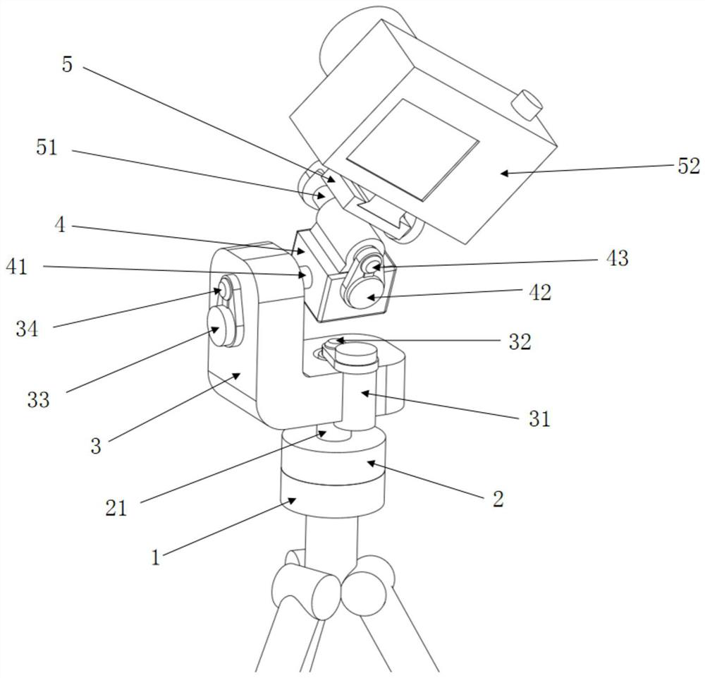
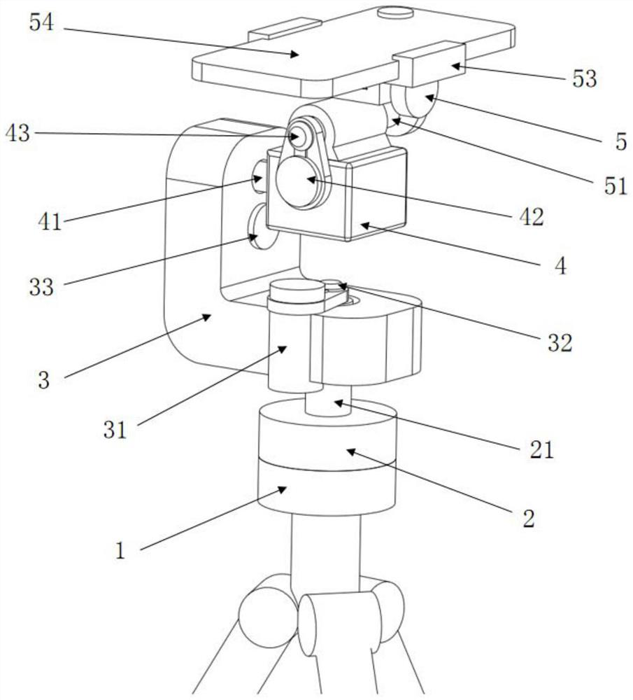
[0043] Example: such as figure 1 , 2 Shown, a kind of system method of the earth rotation motion compensating device that the present invention is used for astrophotography comprises the following steps:

[0044] (1). An azimuth rotation mechanism, a pitch rotation mechanism, a roll angle rotation mechanism, a camera and an intelligent controller of the equatorial mount are set on the mounting base 2 of the equatorial mount. The azimuth rotation mechanism includes an azimuth rotating shaft 21, an azimuth Angle and pitch angle shaft box 3, first drive motor 31 and first rotation angle sensor 32; pitch angle rotation mechanism includes pitch angle shaft 41, roll angle shaft box 4, second drive motor 33 and second rotation angle The sensor 34; the roll angle rotation mechanism includes a roll angle rotation shaft 51, a roll angle rotation shaft casing 4, a third drive motor 42, a third rotation angle sensor 34 and a camera block arranged on the roll angle rotation axis casing 4....


PUM


Abstract

The invention relates to an earth rotation motion compensation system method for astrophotography, which includes an azimuth rotation mechanism, a pitch angle rotation mechanism, a roll angle rotation mechanism, a camera and an intelligent controller of an equatorial mount. The numerical control linkage of the motor and the rotation angle sensor realizes the effect of compensating the earth's rotation, and provides a new method of polar axis alignment. The present invention saves the adjustable base and the camera platform of the prior art, and the degree of freedom of rotation of the overall structure is reduced from 6 to 3, the structure is more compact and light, the rigidity is high, the precision is high, and the operation of polar axis is greatly simplified. And it can realize the electric control of the camera orientation, avoiding the interference that may be caused by the shaking of human hands.

Description

technical field [0001] The invention relates to the technical field of astrophotography equipment, in particular to an earth rotation motion compensation system method for astrophotography. Background technique [0002] In astrophotography activities, the objects of photography are various celestial bodies in the sky such as stars, constellations, nebulae, sun, moon, etc., and the shooting device (camera) is fixed on the earth. Since the objects of astrophotography have low brightness, in order to To take clear images of them usually requires a longer exposure time, and since the camera is set up on the earth, it will rotate with the earth around the earth's polar axis, resulting in a celestial body relative to the camera. Rotational movement in the opposite direction of the axis, in long-time exposure, such movement will cause blurring and smearing of celestial objects in the camera, destroying the quality of photographic works; Compensation; in the prior art, such as pate...

Claims


Application Information

Patent Timeline
Patent Type & Authority Patents(China)
IPC IPC(8): G03B17/56F16M11/12F16M11/18F16M11/04H04M1/04
CPCF16M11/12F16M11/18F16M11/043H04M1/04G03B17/561
Inventor 黄豪
Owner 黄豪
Why Eureka
Try Eureka