
Dehumidifying device and dehumidifying module

a technology of dehumidifying device and dehumidifying module, which is applied in the direction of lighting and heating apparatus, heating types, separation processes, etc., can solve the problems of reducing the efforts of dehumidifying device production control, affecting the design of dehumidifying device, and affecting the effect of design chang

Active Publication Date: 2017-09-05
NABLESCO CORP
View PDF33 Cites 1 Cited by
  • Summary
  • Abstract
  • Description
  • Claims
  • Application Information

AI Technical Summary

Benefits of technology

[0010]The aforementioned techniques allow an easy design change of a dehumidifying device so as to meet dehumidification performance requirement from a user using the dehumidifying device.

Problems solved by technology

Consequently, a manufacturer has to put a lot of efforts for production control of dehumidifying devices.
If the maximum dehumidification performance among the requirements for dehumidifying devices is given to all the types of dehumidifying devices, there may be a decrease in the efforts for the production control of dehumidifying devices.
In this case, however, the dehumidifying devices may be oversized unnecessarily.

Method used


Image

  • Dehumidifying device and dehumidifying module
  • Dehumidifying device and dehumidifying module
  • Dehumidifying device and dehumidifying module

Examples


Embodiment Construction

[0018]An exemplificative dehumidifying device is described with reference to the drawings. In the following description, a dehumidifying device is used for dehumidifying compressed air for use in a railway vehicle. The dehumidifying device, however, may be used for other applications. The following principle of the dehumidifying device is not limited to a specific application of the dehumidifying device.

[Overall Configuration]

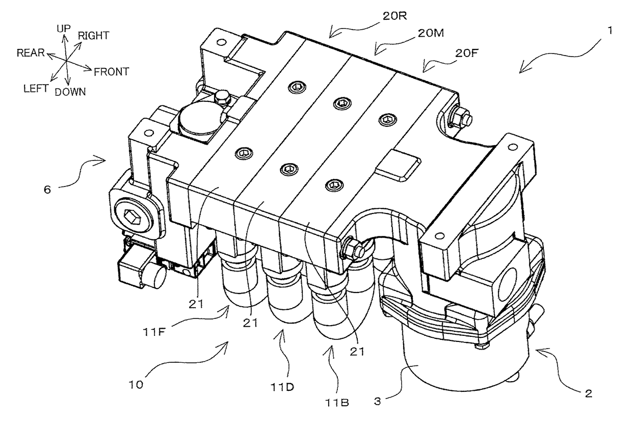
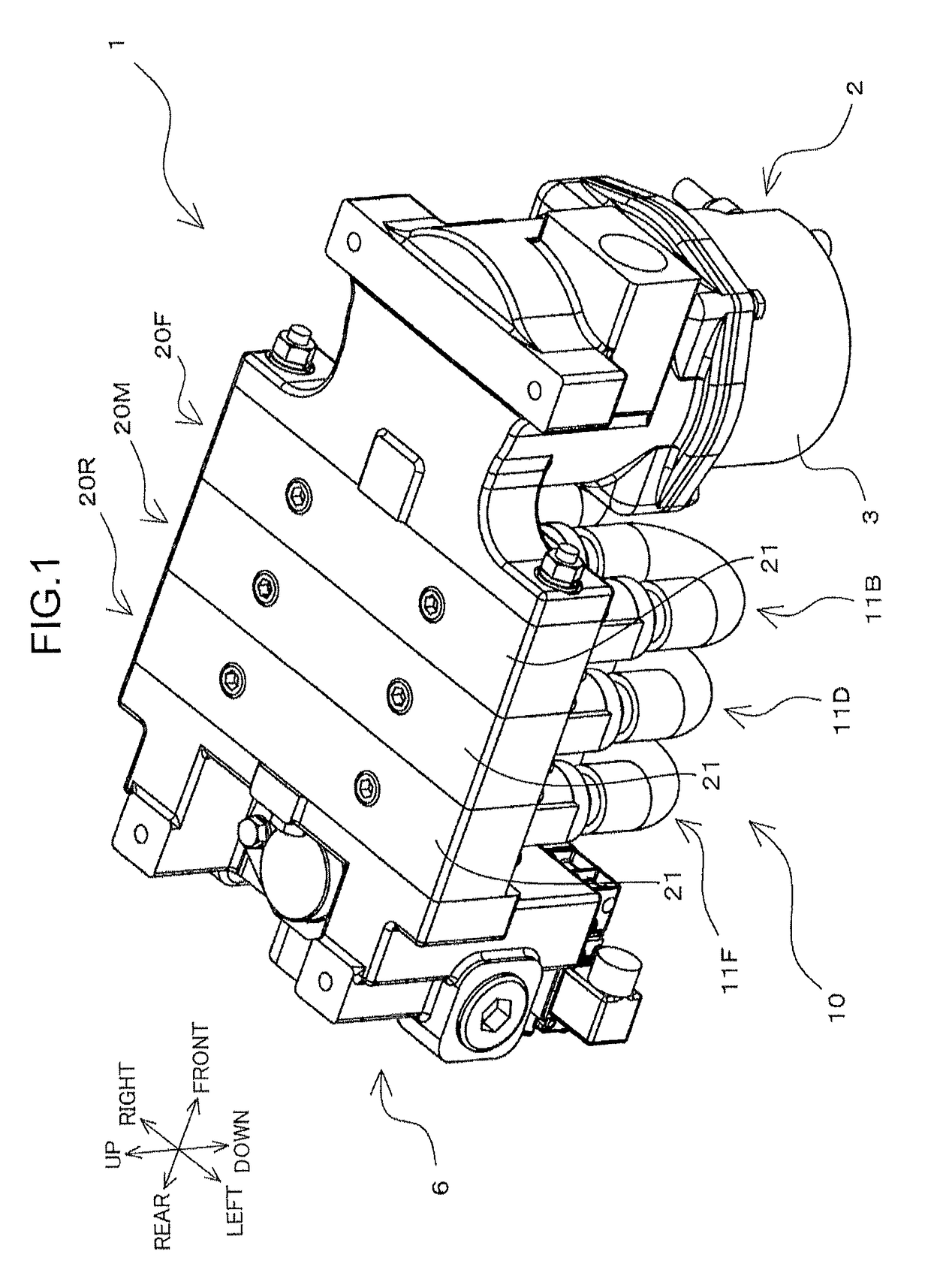
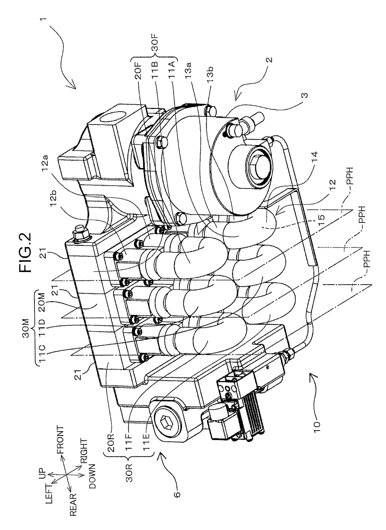
[0019]FIGS. 1 and 2 are schematic perspective views of an exemplificative dehumidifying device 1. FIG. 1 mainly shows an upper portion of the dehumidifying device 1. FIG. 2 mainly shows a lower portion of the dehumidifying device 1. FIG. 3 is a schematic plan view of the dehumidifying device 1. FIG. 4 is a schematic enlarged view of the dehumidifying device 1 shown in FIG. 3 around a dehumidifying unit 10. FIG. 5 is a schematic right side view of the dehumidifying device 1. A part of components is removed from the dehumidifying device 1 shown in FIG. 5. Therefo...


PUM


Abstract

The present application discloses a dehumidifying device including a base configured to define an inlet channel for first air flow, and an outlet channel for second air flow less humid than the first; and a first dehumidifier including a first inlet and outlet in communication with the inlet and outlet channel, and configured to dehumidify the first air between the first inlet and the first outlet to generate the second air. The base includes a first base portion configured to define first inlet and outlet regions for the first and second air flows; and a second base portion configured to define second inlet and outlet regions in communication with the first inlet and outlet regions. The first and second inlet regions form at least a part of the inlet channel. The first and second outlet regions form at least a part of the outlet channel.

Description

BACKGROUND OF THE INVENTION[0001]Field of the Invention[0002]The present invention relates to a dehumidifying device for dehumidifying the air, and a dehumidifying module for use in the dehumidifying device.[0003]Description of the Related Art[0004]Japanese Utility Model Registration No. 3150077 (hereinafter, called as Patent Document 1) discloses a dehumidifying device for dehumidifying compressed air which causes a braking force in a railway vehicle. In Patent Document 1, the air compressed by an air compression unit is cooled by an after-cooler. After the compressed air is cooled, the compressed air is dehumidified by the dehumidifying device, and the compressed air after the dehumidification is stored in a compressed air tank.[0005]FIG. 3 of Patent Document 1 discloses a columnar dehumidifying device. The size (length and diameter) of the dehumidifying device is determined to meet required dehumidification performance. If there is a change in the required dehumidification perfor...

Claims


Application Information

Patent Timeline
Patent Type & Authority Patents(United States)
IPC IPC(8): B01D53/22B01D63/04B01D53/26F24F3/14B60T17/00B61H13/34
CPCB01D53/268B60T17/004B61H13/34F24F3/14B01D63/04F24F2003/1435
Inventor MIZUFUNE, TORUKUROMITSU, MASARUTAKAHASHI, AKIRAMIYAUCHI, TATSUO
Owner NABLESCO CORP
Learn More