Ultrasound diagnostic apparatus, sound velocity setting method, and recording medium

a technology setting method, which is applied in the field of ultrasonic diagnostic equipment, can solve the problems of increasing the amount of calculation, the calculation processing cannot keep up with the setting of sound velocities, and the amount of calculation for setting sound velocities in a subject can be suppressed, and the image quality is higher. , the effect of stably

Active Publication Date: 2017-09-12
FUJIFILM CORP
View PDF8 Cites 2 Cited by
  • Summary
  • Abstract
  • Description
  • Claims
  • Application Information

AI Technical Summary

Benefits of technology

[0017]As described above, setting a sound velocity for each local region in a subject makes it possible to produce a high quality ultrasound image. As the size of the local regions is smaller, the image quality of the ultrasound image can be higher. However, as the size of the local regions is smaller, it increases the amount of calculation for setting sound velocities, which may cause a problem that, for instance, the calculation processing cannot keep up with the setting of sound velocities.
[0018]An object of the present invention is to solve the foregoing problem of the prior art and, as the first aspect, to provide an ultrasound diagnostic apparatus capable of suppressing the amount of calculation for setting sound velocities therein, and appropriately updating sound velocities even when setting a sound velocity for each of small local regions in a subject, thereby stably maintaining a high quality ultrasound image.
[0019]An object of the present invention is, as the second aspect, to provide a sound velocity setting method capable of suppressing the amount of calculation for setting sound velocities in the ultrasound diagnostic apparatus, and appropriately updating sound velocities even when setting a sound velocity for each of small local regions in a subject, thereby stably maintaining a high quality ultrasound image.
[0020]An object of the present invention is, as the third aspect, to provide a recording medium storing a computer program capable of suppressing the amount of calculation for setting sound velocities in the ultrasound diagnostic apparatus, and appropriately updating sound velocities even when setting a sound velocity for each of small local regions in a subject, thereby stably maintaining a high quality ultrasound image.
[0053]Therefore, according to the present invention, even when a sound velocity is set for each of small local regions in a subject for the purpose of higher image quality, the set sound velocities can be appropriately updated to stably maintain a high quality ultrasound image.

Problems solved by technology

Accordingly, the update of sound velocities is a great burden on the ultrasound diagnostic apparatus.
However, as the size of the local regions is smaller, it increases the amount of calculation for setting sound velocities, which may cause a problem that, for instance, the calculation processing cannot keep up with the setting of sound velocities.

Method used


Image

  • Ultrasound diagnostic apparatus, sound velocity setting method, and recording medium
  • Ultrasound diagnostic apparatus, sound velocity setting method, and recording medium
  • Ultrasound diagnostic apparatus, sound velocity setting method, and recording medium

Examples


Embodiment Construction

[0060]An ultrasound diagnostic apparatus, a sound velocity setting method, and a recording medium of the invention will be described in detail below with reference to the preferred embodiments shown in the accompanying drawings.

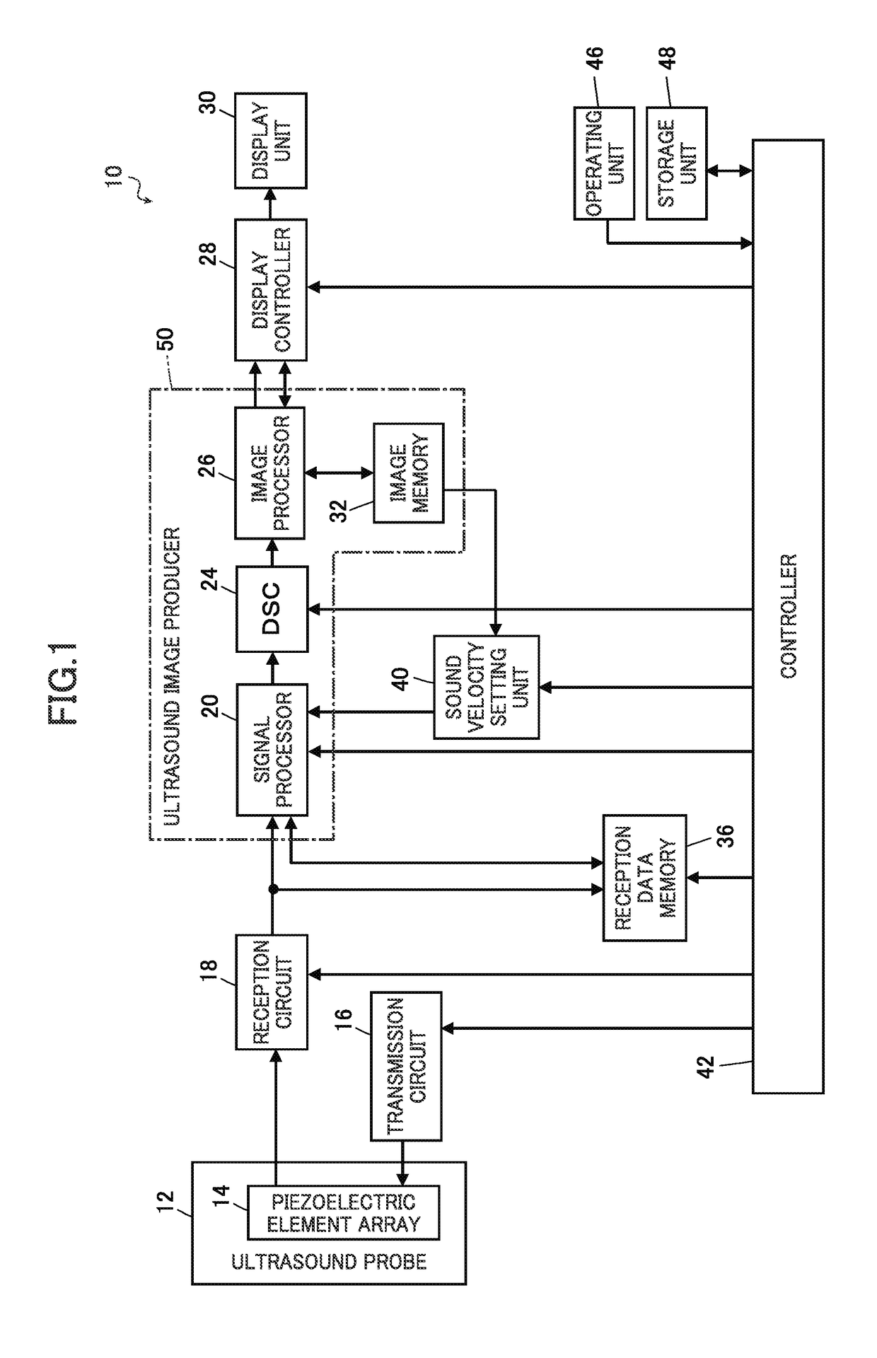
[0061]FIG. 1 is a block diagram conceptually showing an example of an ultrasound diagnostic apparatus of the invention which performs a sound velocity setting method of the invention.

[0062]As shown in FIG. 1, an ultrasound diagnostic apparatus 10 has an ultrasound probe 12 (hereinafter called “probe 12”) including a piezoelectric element array 14.

[0063]The piezoelectric element array 14 of the probe 12 is connected to a transmission circuit 16 and a reception circuit 18. The reception circuit 18 is connected in sequence to a signal processor 20, a digital scan converter (DSC) 24, an image processor 26, a display controller 28, and a display unit 30. The image processor 26 is connected to an image memory 32.

[0064]The signal processor 20, the DSC 24, the image ...


PUM


Abstract

An ultrasound diagnostic apparatus performs transmission and reception of ultrasonic waves for forming focal points used to set sound velocities at predetermined timing such that sound velocities having been set for all of respective segment regions established by dividing a subject are all reset every predetermined number of frames. Owing to this configuration, it becomes possible for the ultrasound diagnostic apparatus to suitably reset sound velocities of ultrasonic waves in the subject and also reduce the amount of calculation for resetting sound velocities.

Description

BACKGROUND OF THE INVENTION[0001]The present invention relates to an ultrasound diagnostic apparatus, particularly to an ultrasound diagnostic apparatus, a sound velocity setting method, and a recording medium for setting sound velocities of ultrasonic waves in a subject.[0002]Ultrasound diagnostic apparatuses using ultrasound images are put to practical use in the medical field.[0003]In general, this type of ultrasound diagnostic apparatus includes an ultrasound probe (hereinafter also called “probe”) having a piezoelectric element array in which piezoelectric elements transmitting and receiving ultrasonic waves are arranged, and a diagnostic apparatus body.[0004]The ultrasound diagnostic apparatus transmits ultrasonic waves from the probe into a subject's body, receives the ultrasonic echo from the subject with the probe, and electrically processes the resulting reception signals with the diagnostic apparatus body to produce an ultrasound image.[0005]The piezoelectric element arra...

Claims


Application Information

Patent Timeline
Patent Type & Authority Patents(United States)
IPC IPC(8): A61B6/00A61B8/14A61B8/00A61B8/08G01S7/52
CPCA61B8/585A61B8/14A61B8/5207A61B8/5269A61B8/54G01S7/52049G01S7/52085A61B8/4483
Inventor OHTA, YASUNORITANABE, TSUYOSHIIDA, NORIAKINAKATA, SHINYAMAGUCHI, HIROSHI
Owner FUJIFILM CORP
Why Eureka
Try Eureka