Foot compression and electrical stimulation system

a compression and electrical stimulation technology, applied in the field of foot compression and electrical stimulation systems, can solve the problems of pulmonary embolism, ulcers, and pulmonary embolism, and achieve the effect of increasing circulation

Active Publication Date: 2017-09-12
AVEX GROUP
View PDF97 Cites 6 Cited by
  • Summary
  • Abstract
  • Description
  • Claims
  • Application Information

AI Technical Summary

Benefits of technology

[0005]A compression and electrical stimulation system is configured to apply pressure to a foot and electrically stimulate the muscles of the same or surrounding areas (e.g., foot and leg) to contract, for example in order to increase circulation. In an exemplary embodiment, a system configured in accordance with principles of the present disclosure comprises an actuator portion comprising a retractable, non-bendable pressure pad and an electrical muscle stimulator that may optionally be combined with a compression garment. Another exemplary embodiment further comprises an item of footwear, wherein the actuator portion is completely contained within the item of footwear. Similarly, in other exemplary embodiments, the electrical muscle stimulator is completely contained within an item of footwear.
[0006]In various exemplary embodiments, a compression and stimulation system configured in accordance with principles of the present disclosure may be utilized for one or more of athletic warm-up or recovery, the removal of metabolic waste, wound care and recovery, or the treatment of medical conditions including plantar fasciitis, restless leg syndrome, deep vein thrombosis, pulmonary embolism, venous insufficiency, and / or the like.

Problems solved by technology

If a person is immobilized, unable to move regularly, or has poor circulation brought on by disease, the natural blood return mechanism is impaired, and circulatory problems such as ulcers, deep vein thrombosis, and pulmonary embolisms can occur.

Method used


Image

  • Foot compression and electrical stimulation system
  • Foot compression and electrical stimulation system
  • Foot compression and electrical stimulation system

Examples


Embodiment Construction

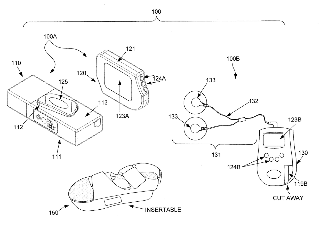
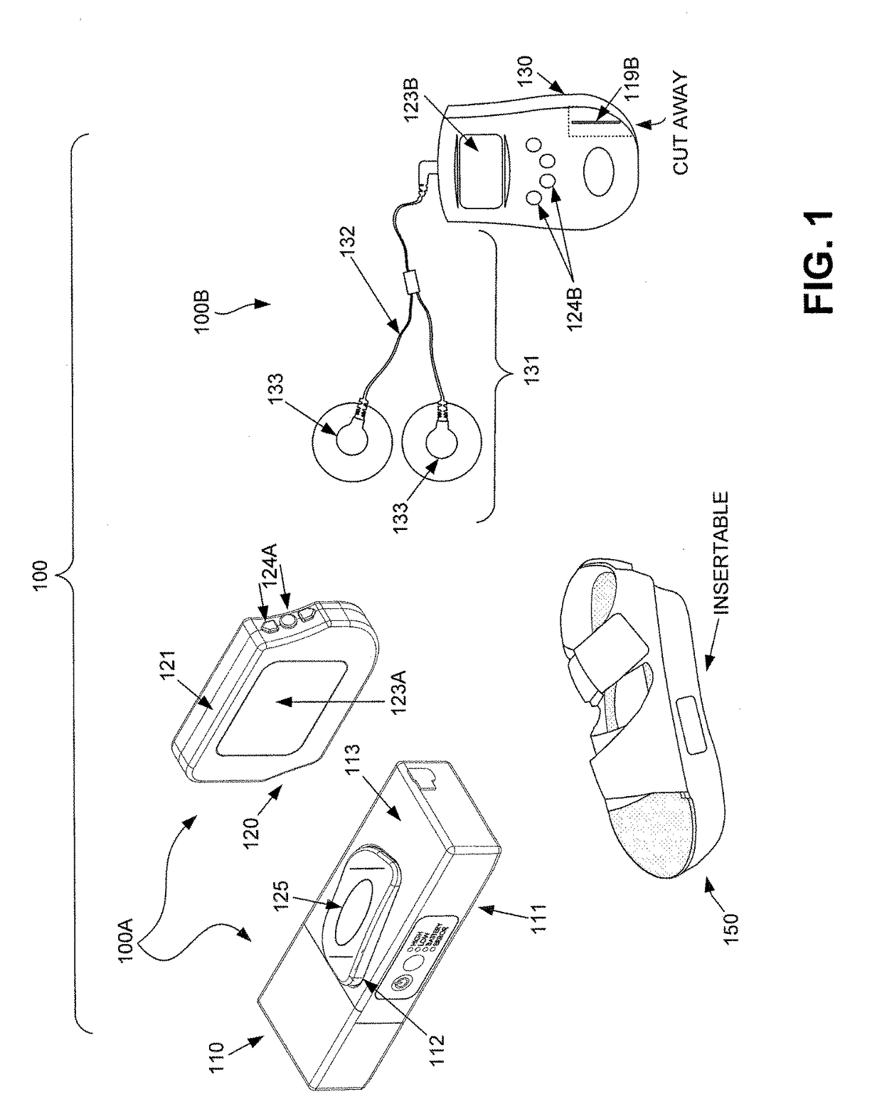
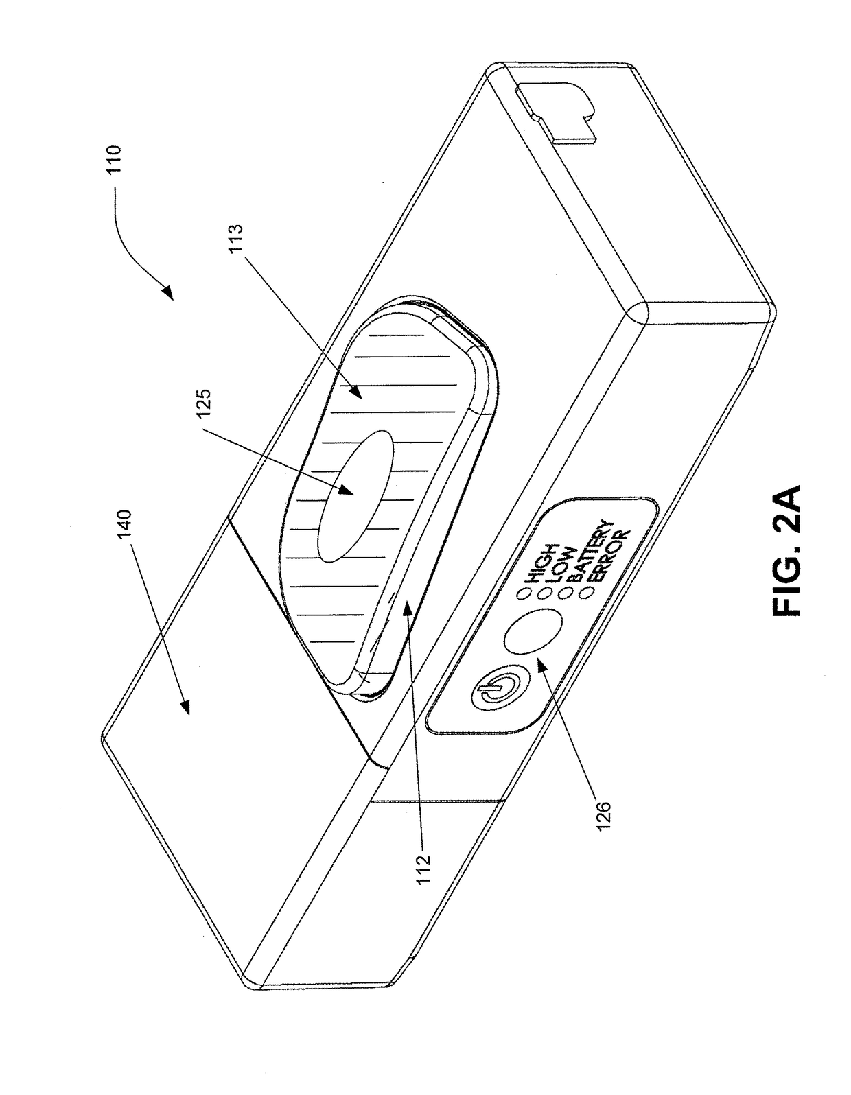
[0023]Details of the present disclosure may be described herein in terms of various components and processing steps. It should be appreciated that such components and steps may be realized by any number of hardware and / or software components configured to perform the specified functions. For example, the system may employ various medical treatment devices, input and / or output elements and the like, which may carry out a variety of functions under the control of one or more control systems or other control devices. In addition, details of the present disclosure may be practiced in any number of medical or treatment contexts, and exemplary embodiments relating to a compression and stimulation system, for example usable in connection with treatment of deep vein thrombosis, or in connection with athletic recovery, as described herein are merely a few of the exemplary applications. For example, the principles, features and methods discussed may be applied to any medical or other tissue o...


PUM


Abstract

Systems configured to apply pressure to a foot and electrically stimulate muscles to contract in order to increase circulation and facilitate removal of metabolic waste, and related methods, are disclosed. One exemplary embodiment comprises an actuator that repeatedly compresses the bottom of a foot and an electrical muscle stimulator that repeatedly sends electrical pulses to a muscle to facilitate a muscle contraction. The system may also include a compression garment, such as a compression sock to be worn while undergoing both the repeated compression cycles and the repeated electrical pulses. The system may also include an item of footwear, wherein the actuator portion is partially or completely contained within the item of footwear. Additionally and/or alternatively, the electrical muscle stimulator may be partially or completely contained within the item of footwear.

Description

CROSS-REFERENCE TO RELATED APPLICATIONS[0001]This application is a continuation of PCT Application No. PCT / US2012 / 050290 having an international filing date of Aug. 10, 2012 and entitled “FOOT COMPRESSION AND ELECTRICAL STIMULATION SYSTEM”. PCT Application No. PCT / US2012 / 050290 claims priority to U.S. Provisional Application No. 61 / 523,023 filed on Aug. 12, 2011 and entitled “FOOT COMPRESSION AND ELECTRICAL STIMULATION SYSTEM”. The entire contents of all the foregoing applications are hereby incorporated by reference.TECHNICAL FIELD[0002]The present disclosure generally relates to systems and methods for creating a similar amount of blood flow to a part of the body, such as the legs and feet, as would be experienced during muscle contraction and movement, such as walking. To this end, the present disclosure generally relates to systems and methods for mechanically compressing an area of the body, such as the venous plexus region in the arch of the foot, and the superficial veins of ...

Claims


Application Information

Patent Timeline
Patent Type & Authority Patents(United States)
IPC IPC(8): A61H1/00A61N1/04A61N1/32A61N1/36
CPCA61H1/008A61N1/0452A61N1/0484A61N1/0492A61N1/322A61N1/36003A61N1/36014A61N1/36031
Inventor MAYER, MATTHEW J.
Owner AVEX GROUP
Why Eureka
Try Eureka