Vehicle lifting and parallel parking aid

a technology for parallel parking and vehicles, applied in vehicle maintenance, vehicle components, tire measurements, etc., can solve the problems of increasing the cost of vehicles, parallel parking systems can be expensive, and system implementation requires additional cost of controllable steering (i.e. electric power steering), controllable brakes, and controllable throttles

Active Publication Date: 2017-09-12
INNOVATIVE INVENTIONS
View PDF66 Cites 4 Cited by
  • Summary
  • Abstract
  • Description
  • Claims
  • Application Information

AI Technical Summary

Benefits of technology

[0016]A vehicle lifting and parking aid system having a sidewinder wheel unit mounted between the brakes and the spindle of each wheel of a vehicle controlled from a control module located within the vehicle is disclosed. Each sidewinder wheel unit is comprised of a touch-down wheel, sidewinder wheel, DC electric high torque motor, a positioning system (motor driven rotating gears and lift gears), and a solenoid operated locking pin. In general, the device rotates between a storage position and a deployed position. In the storage position, the device is positioned under the vehicle so that it does not impair normal operation of the vehicle. When deployed, the device rotates about the axle or spindle until a touch-down wheel, aligned with the longitudinal centerline of the vehicle, lifts the primary wheels of the vehicle about one half inch off of the ground surface. Thereafter, the device is locked into place by the solenoid operated locking pin. Once positioned and locked into the deployed position, the sidewinder wheel is positioned against the ground surface, lifting the touchdown wheel off the ground. The sidewinder wheel has its center of axis perpendicular to the ground surface and transverse with respect to the longitudinal axis of the vehicle, whereby rotation thereof moves the vehicle to the left or right. By way of the second solenoid, the motor switches from operating the lifting gear train to the rotating gear train. Using joysticks on the control module located within the vehicle, the user is capable of initiating rotation of the sidewinders about a vertical axis. This construction permits the operator to move the vehicle in any direction along a surface. Accordingly, it is a primary objective of the instant invention to provide a vehicle lifting and parking aid system that allows vehicles to be moved sideways without turning the vehicle's wheels or altering the power train or design.
[0017]It is a further objective of the instant invention to provide a vehicle lifting and parking aid system that aids in parallel parking within a space of equal length of the vehicle, as opposed to the typical one and half car-length long space without the use of expensive sensors, and capable of parallel parking.
[0018]It is yet another objective of the instant invention to provide a vehicle lifting and parking aid system that will stop the vehicle from going out of control when a tire blow-out occurs, since the touch-down wheel immediately makes contact with the road and functions in place of the blown out tire until the vehicle is driven to an area of safety.
[0019]It is a further objective of the instant invention to provide a vehicle lifting and parking aid system that, while in an engaged position, allows one to change tires, brakes, axles, or the like without the use of a jack or expensive lifting and lowering system.
[0022]It is yet still another objective of the instant invention to provide a vehicle lifting and parking aid system that will enable the vehicle to be moved safely.
[0023]It is yet another additional objective of the instant invention to provide a vehicle lifting and parking aid system that will move a vehicle from a cramped space under battery power.

Problems solved by technology

Parallel parking allows a vehicle to park in a smaller space than with side-by-side parking, which is common in many public parking facilities, but often equally as challenging because of the action of other drivers.
Such a system must be built into the vehicle during manufacturing, thereby increasing the cost of the vehicle.
These parallel-parking systems can be expensive due to the cost of the multiple sensors and the controller touch-down that processes the algorithms.
In addition, the system implementation requires the additional cost of controllable steering (i.e. electric power steering), controllable brakes, and controllable throttles.
Some car owners choose to cut the manufacturers' coil suspension springs instead, but this method can cause the springs to weaken and even fail, resulting in an uneven or dangerous ride.
This practice can eventually cost more because it may throw off a car's alignment, resulting in wear and tear on supporting parts like the frame, tires and undercarriage.
Overall, the lifting and lowering of a vehicle can be very expensive, especially for the vehicle owner not interested in the aesthetic or functional appeal of an off-road truck, low-rider, or trick car.
However, providing a lifting and lowering system to perform mechanical services, such as tire, brake, or axle repair, parts replacement, or maintenance in an emergency should not be ignored because of financial or manufacturer restrictions.
The drawbacks associated therewith are that the runner is limited in distance the vehicle can be moved; and when moved, the frame can become dismounted from the chassis because of the load placed upon it.
The drawbacks associated therewith include an uneven drive created during emergency situations and, since the auxiliary wheels do not elevate the chassis sufficiently, there is a limited clearance should a tire explode.
The jacking systems above fulfill their respective objectives; however, none of the lifting systems described above address the safety issue of removing the vehicle from harms way in the event of an emergency on a busy road.
Thus, what is lacking in the art is an efficient, cost effective parking system that is capable of lifting a vehicle and assisting in the process of parallel parking.

Method used


Image

  • Vehicle lifting and parallel parking aid
  • Vehicle lifting and parallel parking aid
  • Vehicle lifting and parallel parking aid

Examples


Embodiment Construction

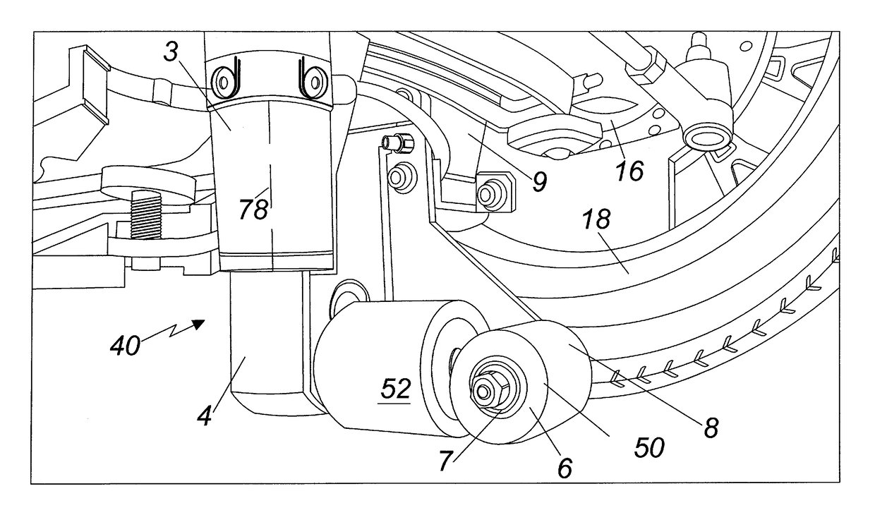
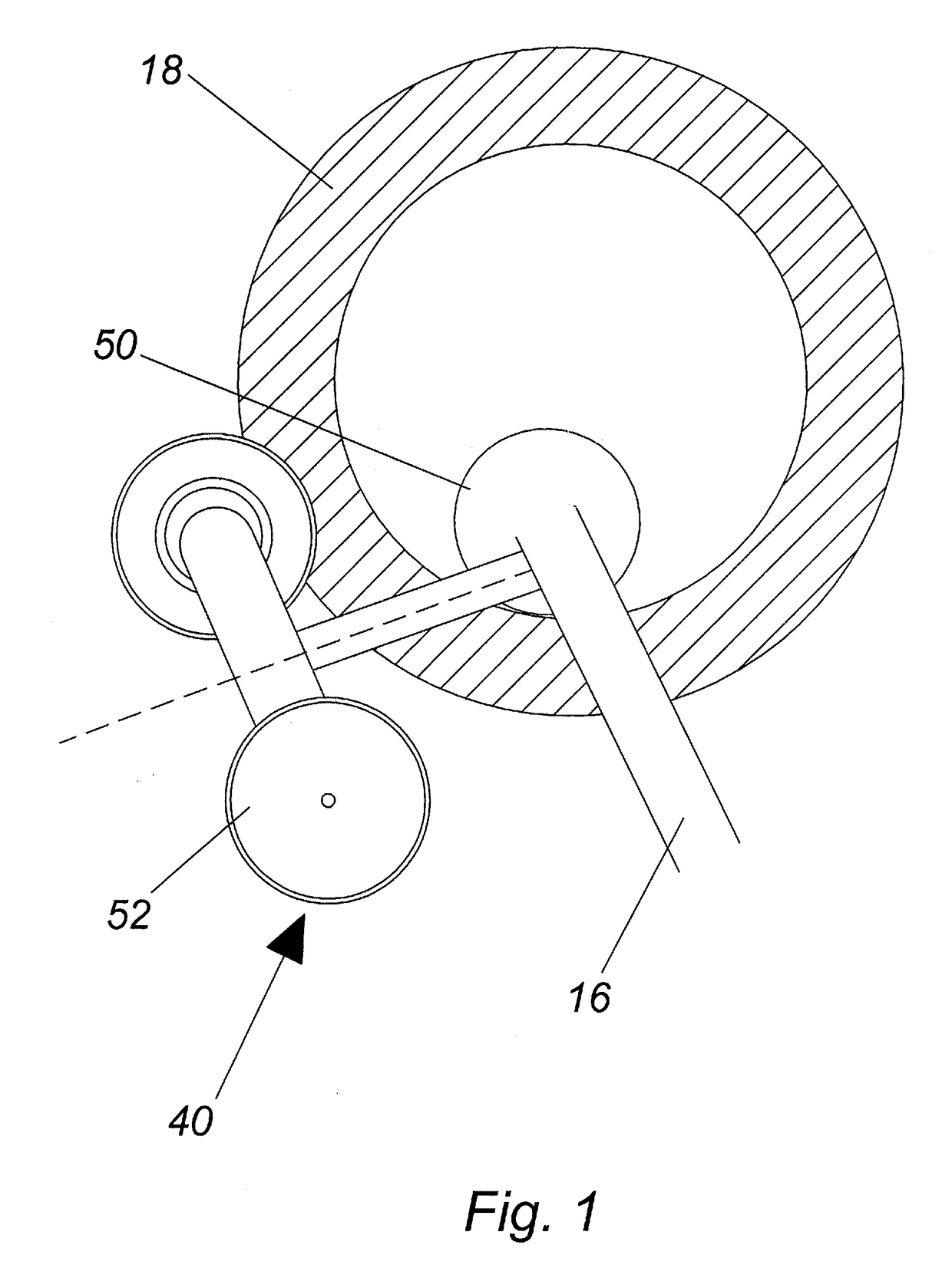
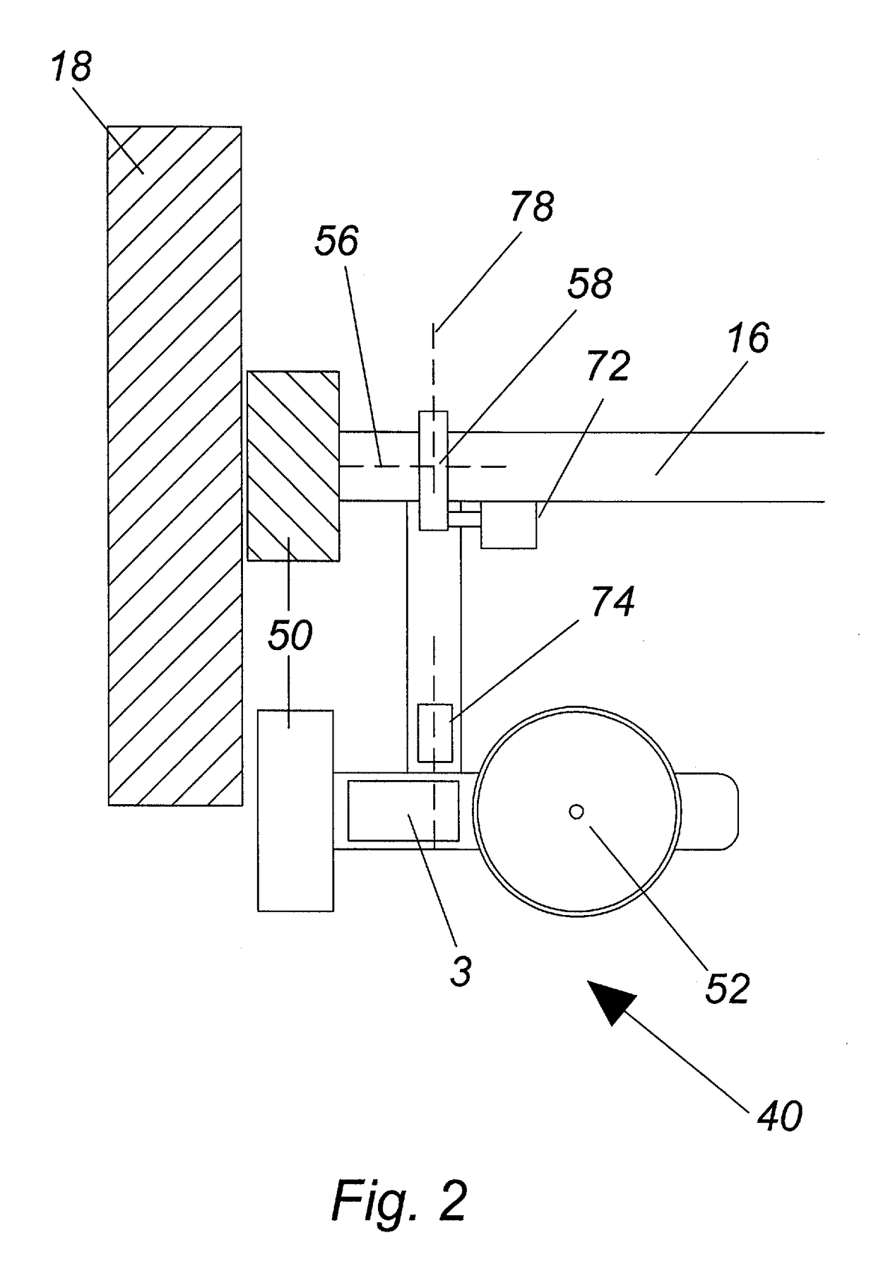
[0037]As shown in FIGS. 1-11, each sidewinder unit 40 includes a sidewinder wheel 52, a touch-down wheel 50, a high torque electric DC motor 3 which may include a gear drive 4, a first solenoid 72 for locking in the retracted and engaged positions of the sidewinder unit, and a second solenoid 74 to move the high torque electric DC motor 3 between the gearing system (from a lifting gear train to a rotating gear train). The four sidewinder units 40 are contemplated to weigh no more than 250 to 300 lbs. depending on the size and demands of each vehicle. The sidewinder unit is powered by external batteries 60, 62 (FIGS. 4 and 5), and coupled to a control module 100 (FIG. 6) located inside of the vehicle. It is contemplated that the external batteries 60, 62 be stored in the trunk of the vehicle. Each sidewinder unit 40 contains its own gearing systems 4, 5. The gearing system is comprised of motor driven rotating gears 4 and lifting gears 5 (don't see on a FIG). The motor driven rotatin...


PUM


Abstract

A vehicle lifting and parking aid system having sidewinder wheel units mounted on the axles between the brakes and the spindle of each wheel of a vehicle controlled from a control module located within the vehicle is disclosed. In the deployed position, each sidewinder unit is against the ground surface and lifts the vehicle approximately 0.5″ off the ground. Using joysticks on a control module located within the vehicle, the user is able to operate, i.e. direct, the sidewinders to the left or right at different variations in speed whereby the vehicle is moved to the left or right by way of a rotating gear train.

Description

PRIORITY CLAIM[0001]In accordance with 37 C.F.R. 1.76, a claim of priority is included in an Application Data Sheet filed concurrently herewith. Accordingly, the present invention application claims priority to U.S. Provisional Application No. 61 / 936,224, entitled “Vehicle Lifting and Parallel Parking Aid” filed Feb. 5, 2014, the contents of which are incorporated herein in their entirety.FIELD OF THE INVENTION[0002]This invention relates generally to the field of automotive accessories, and in particular to a vehicle lifting and parallel parking aid.BACKGROUND OF THE INVENTION[0003]Parallel parking, considered to be one of the most challenging maneuvers for new drivers to learn, is a method of parking a vehicle in line with other parked vehicles. Parallel parking requires driving the vehicle slightly past the parking space, parallel to the vehicle parked in front of that space and then, while maintaining a safe distance, reversing into the chosen space. Subsequent position adjustme...

Claims


Application Information

Patent Timeline
Patent Type & Authority Patents(United States)
IPC IPC(8): B60S9/14B60S9/215B60C23/00
CPCB60S9/215B60C23/006B60S9/14
Inventor MISTROT, DON A.DUFFIELD, RICHARD P.
Owner INNOVATIVE INVENTIONS
Why Eureka
Try Eureka