Gate valve arrangement including multi-valve stem and seat assemblies

a multi-valve stem and seat technology, applied in the direction of spindle sealing, sealing/packing, borehole/well accessories, etc., can solve the problems of metal sealing, premature wear, and unnecessary longevity

Active Publication Date: 2017-09-12
VETCO GRAY
View PDF37 Cites 12 Cited by
  • Summary
  • Abstract
  • Description
  • Claims
  • Application Information

AI Technical Summary

Benefits of technology

[0010]The gate valve further includes two multi-valve sealing assemblies, including a stem seal assembly and a seat seal assembly. In certain embodiments, the stem seal assembly includes a cartridge body and multiple seals, including a primary metal stem seal, a secondary stem seal, and a tertiary metal stem seat. In alternate embodiments, the stem seal assembly may include two, rather than three, seals, depending on factors such as cost and reliability requirements. Each seal is configured to help seal the space between the stem and the bonnet. Together, the primary, secondary, and tertiary stem seals form a redundant system that maintains a sealed interface between the stem and the bonnet, even if some of the seals fail. In addition, the seat seal assembly may include a check line fluidly connecting the stem seal assembly to the environment through the bonnet. The check line is configured to allow any fluids that leak into the stem seal assembly to escape to the environment. Check line seals may be provided to seal between the cartridge body and the bonnet, thereby preventing the backflow of fluids from the environment into the stem seal assembly.
[0012]In addition to the seat seals, there is also provided a sand excluder between the seat ring and the valve body adjacent the flow passageway. The sand excluder has an excluding arm that is maintained in contact with the valve body by a biased spring. The purpose of the sand excluder is to prevent sand or other solid particles from entering the space between the seat ring and the valve body where it can damage the seals or cause other problems.

Problems solved by technology

However, since elastomeric seals do not have the necessary longevity, especially in corrosive environments, or the ability to withstand high temperatures and pressures, metal seals have become popular.
Metal seals, however, have their own problems, including premature wear, damage to the sealing surfaces, and insufficient sealing capacity under certain conditions.

Method used


Image

  • Gate valve arrangement including multi-valve stem and seat assemblies
  • Gate valve arrangement including multi-valve stem and seat assemblies
  • Gate valve arrangement including multi-valve stem and seat assemblies

Examples


Embodiment Construction

[0030]The foregoing aspects, features, and advantages of the present technology will be further appreciated when considered with reference to the following description of preferred embodiments and accompanying drawings, wherein like reference numerals represent like elements. In describing the preferred embodiments of the technology illustrated in the appended drawings, specific terminology will be used for the sake of clarity. However, the technology is not intended to be limited to the specific terms used, and it is to be understood that each specific term includes equivalents that operate in a similar manner to accomplish a similar purpose.

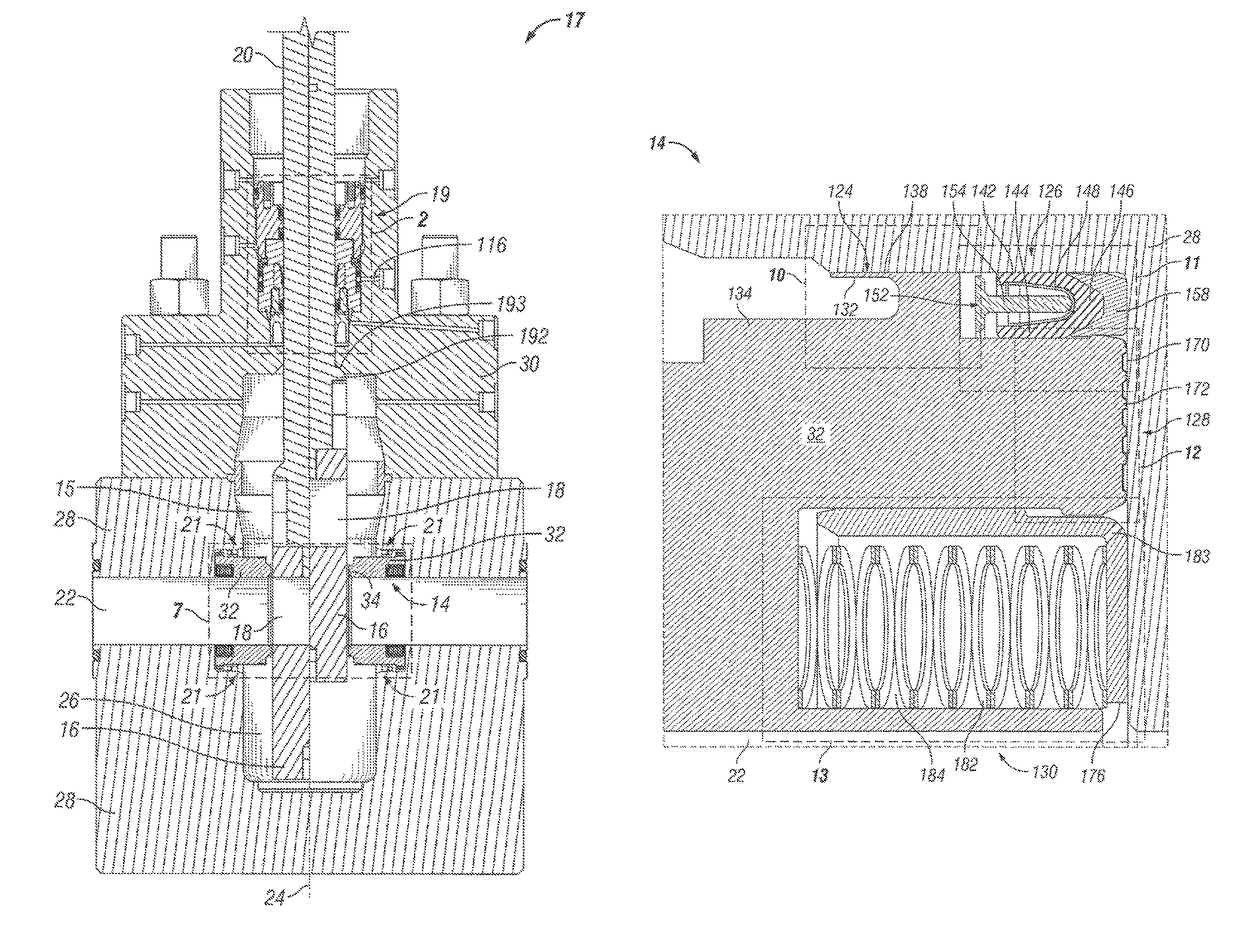
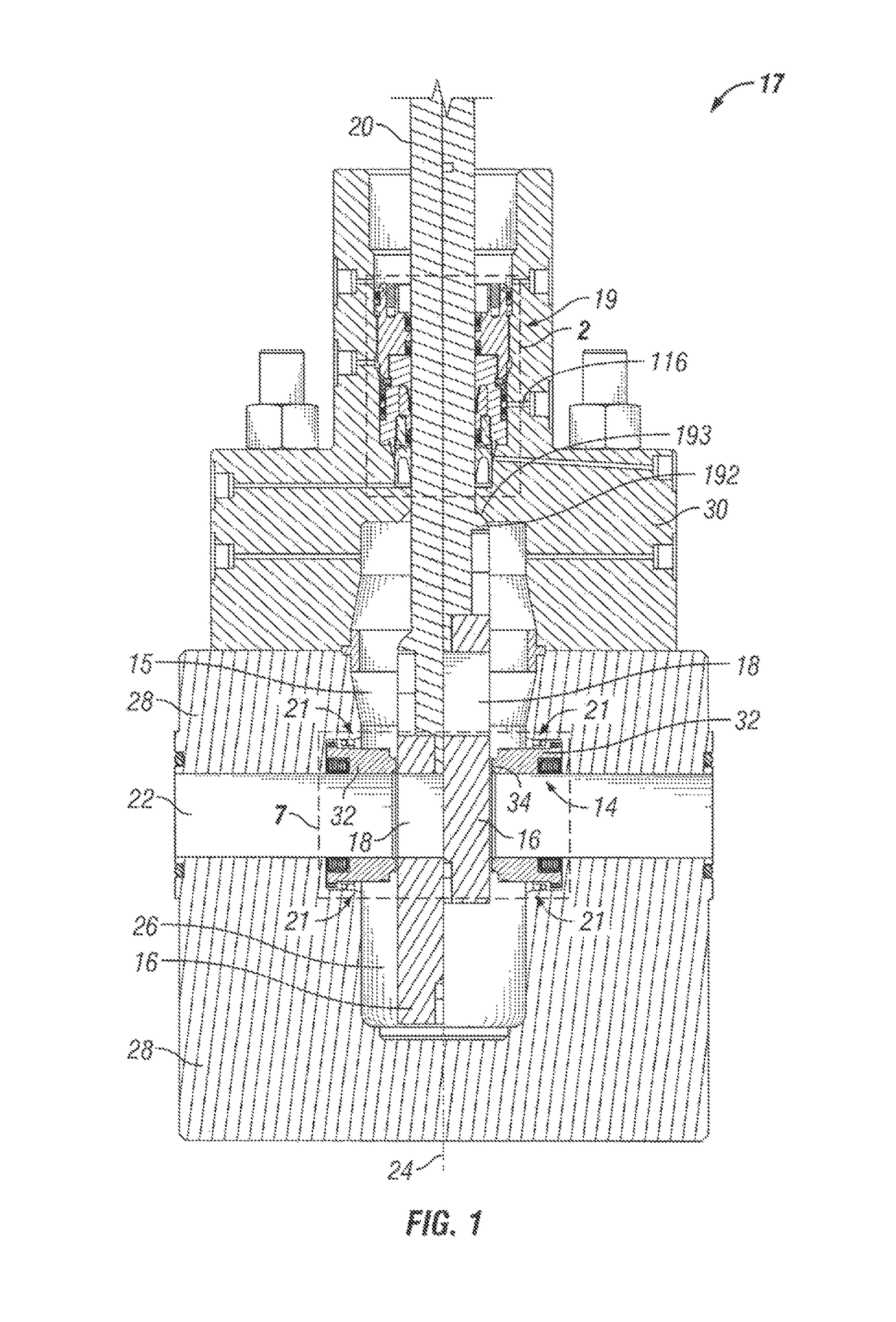
[0031]FIG. 1 shows a side cross-sectional view of a gate valve assembly 17 according to an embodiment of the present technology, including a multi-valve stem seal assembly 19 and a multi-valve seat seal assembly 14. The gate valve assembly 17 includes a gate 16 with an opening 18. The gate 16 is attached to a stem 20, and moves in a central cav...


PUM


Abstract

A gate valve for use in oil field applications and including a stem seal assembly and a seat seal assembly. Each of the stem and seat seal assemblies accommodate independent primary, secondary, and tertiary seals for sealing the space between the stem and the bonnet, or the seat ring and the valve body, respectively. The provision of multiple seals in each assembly provides redundancy that allows for maintenance of the seal between the components even if one or two of the individual seals fail.

Description

CROSS REFERENCE TO RELATED APPLICATIONS[0001]This application claims priority to and the benefit of U.S. Provisional Application Ser. No. 61 / 747,749, which was filed Dec. 31, 2012, the full disclosure of which is incorporated herein by reference.BACKGROUND OF THE INVENTION[0002]1. Field of the Invention[0003]This technology relates to oil and gas wells, and in particular to seals in gate valves used in oil and gas field applications.[0004]2. Brief Description of Related Art[0005]Typical gate valves used in connection with oil and gas operations have a valve body with a flow passageway that extends therethrough. The flow passageway intersects a central cavity, where a gate is located. The gate has an opening, and moves between open and closed positions. When in the open position, the opening is aligned with the fluid path so that fluid can flow therethrough. Conversely, when the gate is in the closed position, the gate blocks the flow passageway. The gate is attached to a stem, which...

Claims


Application Information

Patent Timeline
Patent Type & Authority Patents(United States)
IPC IPC(8): F16K3/02F16K3/30F16K41/08E21B33/00
CPCF16K3/30F16K3/0227F16K3/0236F16K41/08E21B2033/005E21B2200/01F16K3/02F16K3/0281F16K3/0245
Inventor HUNTER, RICK C.KAHN, JON B.TANAKA, FABIO OKAMOTO
Owner VETCO GRAY
Why Eureka
Try Eureka