Image estimating method including calculating a transverse cutoff frequency, non-transitory computer readable medium, and image estimating apparatus

a technology of image estimation and transverse cutoff frequency, which is applied in the field of image estimation method and non-transitory computer readable medium, and image estimation apparatus, can solve the problems of reducing image estimation accuracy, unable to provide an image, and requiring a remarkably long image pickup time, etc., to achieve the effect of easy and precise estimation

Inactive Publication Date: 2017-09-19
CANON KK
View PDF13 Cites 1 Cited by
  • Summary
  • Abstract
  • Description
  • Claims
  • Application Information

AI Technical Summary

Benefits of technology

[0010]The present invention provides an image estimating method, a non-transitory computer readable medium, and an image estimating apparatus, which can easily and precisely estimate an image at an arbitrary position with a small data amount.

Problems solved by technology

Acquiring many images requires a remarkably long image pickup time and a large data amount.
On the other hand, the excessively reduced image pickup number may result in a failure to provide an image at a focus position desired by a doctor in his diagnosis.
However, the image estimating precision may lower when the image acquiring interval becomes excessively wide.
In addition, this method is inapplicable to a partial coherent imaging system as in a microscope.
The polynomial expansion up to a high order becomes necessary to improve the precision of the approximation, but then an extremely long calculation time is required.
As a result, images are obtained at excessively narrow intervals, and a data capacity reducing effect becomes lower.

Method used


Image

  • Image estimating method including calculating a transverse cutoff frequency, non-transitory computer readable medium, and image estimating apparatus
  • Image estimating method including calculating a transverse cutoff frequency, non-transitory computer readable medium, and image estimating apparatus
  • Image estimating method including calculating a transverse cutoff frequency, non-transitory computer readable medium, and image estimating apparatus

Examples


first embodiment

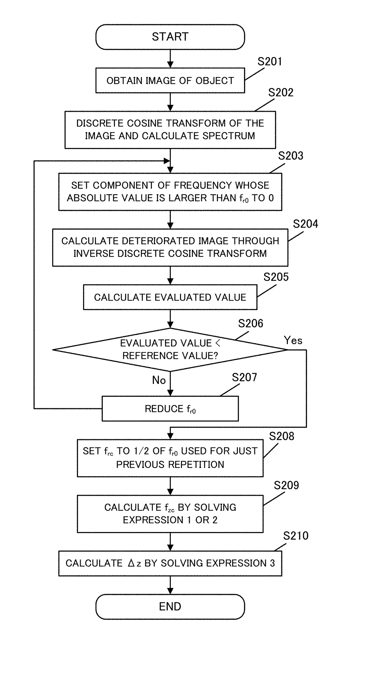
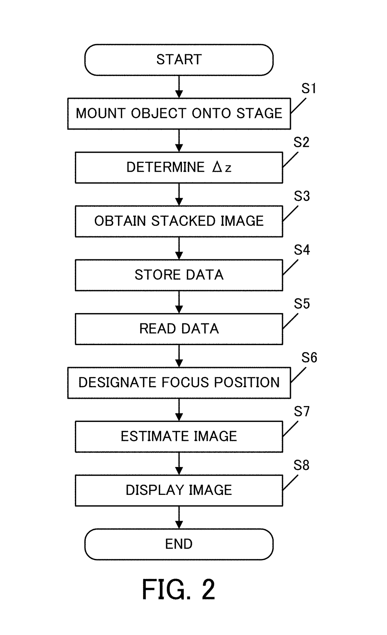
[0062]A description will now be given of an image estimating method at an arbitrary focus position according to a first embodiment. Assume, as conditions of the optical system in this embodiment, that an image-pickup optical system has a numerical aperture NA of 0.25, an imaging magnification is 10 times, and light has a wavelength λ of 650 nm and is monochromatic. Moreover, assume that a partial coherent illumination is used, and a numerical aperture of the illumination optical system NAi satisfies NAi / NA=0.7. A description will be given of a concrete method for determining Δz according to the flowcharts illustrated in FIGS. 2 and 3, and for displaying an image at an arbitrary position. This embodiment exhibits effects through numerical simulations.

[0063]Initially, the amplitude transmittance illustrated in FIG. 5 is set as the object used for the calculation (S1). Two orthogonal coordinates x and y are set which are perpendicular to the optical axis. Next, Δz is set (S2).

[0064]In ...


PUM


Abstract

The image estimating method is configured to estimate, using image data generated by capturing an object via an image-pickup optical system at a plurality of positions that are spaced at first intervals in an optical-axis direction of the image-pickup optical system, image data at a position different from the plurality of positions. The image estimating method includes an image acquiring step of acquiring image data, a frequency analyzing step of calculating a transverse cutoff frequency in a direction perpendicular to the optical-axis direction based on the image data acquired in the image acquiring step, and an interval calculating step of calculating the first interval based on the transverse cutoff frequency calculated by the frequency analyzing step.

Description

BACKGROUND OF THE INVENTION[0001]Field of the Invention[0002]The present invention relates to an image estimating method, a non-transitory computer readable medium, and an image estimating apparatus, for estimating an image at an arbitrary focus position.[0003]Description of the Related Art[0004]In the virtual slide system, a digital image-pickup apparatus called a virtual slide is used to obtain a digital image of an object. In the medical field, an object is generally formed as a prepared specimen in which a sample is covered and fixed by an optical element (a cover glass). The virtual slide includes a microscope optical system, an image sensor, and an information processor, converts a prepared specimen into a digital image, and stores its data. Since this type of device stores only a digital image of the prepared specimen, a viewable image after the pickup is only an image at a focus position used for the pickup. Since a doctor frequently needs to determine a three-dimensional st...

Claims


Application Information

Patent Timeline
Patent Type & Authority Patents(United States)
IPC IPC(8): H04N5/228H04N5/232G06T5/50
CPCH04N5/23212G06T5/50G06T2207/10004G06T2207/10056G06T2207/10148G06T2207/20052G06T2207/20056G06T2207/30024H04N2201/0039
Inventor EGUCHI, AKIRA
Owner CANON KK
Why Eureka
Try Eureka