Ultrasonic bonding method of coated electric wires and ultrasonic bonding apparatus using same

a technology of ultrasonic bonding and electric wire, which is applied in the direction of soldering apparatus, conductor, auxillary welding device, etc., can solve the problems of complex setting of conditions to satisfy both vibration conditions and difficulty in obtaining uniform connection sta

Inactive Publication Date: 2005-08-30
YAZAKI CORP
View PDF25 Cites 6 Cited by
  • Summary
  • Abstract
  • Description
  • Claims
  • Application Information

AI Technical Summary

Benefits of technology

[0008]In this case, by appropriately setting the first vibration condition of the ultrasonic vibration force used in the insulator-melting step and the second vibration condition of the ultrasonic vibration force used in the conductor-bonding step, it is possible melt the insulators and bond the conductors to each other in optimal states. At that time, the contact between the conductors of the coated electric wires can automatically be detected by the conductor contact-detecting step, the conditions can automatically be switched between the insulator-melting step and the conductor-bonding step, a series of connecting operation in which the insulators are melted and removed and the conductors are bonded to each other can easily and stably be carried out.
[0012]In this case, it is possible to precisely detect the contact area between the conductors by the variation in the resistance value between the horn-side chip and the anvil-side chip. Therefore, it is possible easily and precisely estimate the bonding proceeding degree, and to appropriately vary the second vibration condition.
[0014]In this case, in a state in which the intersected portions of the coated electric wires are sandwiched and pressurized between the horn-side chip and the anvil-side chip, if the ultrasonic vibration force is output from the ultrasonic vibrator to the horn-side chip, the intersected portions of the coated electric wires can be melted by the ultrasonic vibration. At that time, the ultrasonic vibration force for melting the insulators is determined by the first vibration condition, and the ultrasonic vibration force for bonding the conductors to each other is determined by the second vibration condition. By setting the first vibration condition and the second vibration condition such that the melting state of the insulators and the bonding state of the conductors become optimal, a series of connecting operation in which the insulators are melted and the conductors a re bonded to each other can easily and stably be carried out.
[0018]In this case, since it is possible precisely detect the contact area between the conductors by the variation of the resistance value between the horn-side chip and the anvil-side chip, it is possible easily and precisely estimate the bonding proceeding degree, and to appropriately vary the second vibration condition.

Problems solved by technology

Therefore, the setting of conditions satisfying both the vibration conditions is complicated, and the condition setting is easily be varied depending upon positional deviation of conductors or setting deviation at the time of pressurization.
Thus, the bonding operation of electric wires largely depends on guesswork or an operator, and it is difficult to obtain uniform connection state.

Method used


Image

  • Ultrasonic bonding method of coated electric wires and ultrasonic bonding apparatus using same
  • Ultrasonic bonding method of coated electric wires and ultrasonic bonding apparatus using same
  • Ultrasonic bonding method of coated electric wires and ultrasonic bonding apparatus using same

Examples


Embodiment Construction

[0023]An embodiment of the present invention will be explained in detail with reference to the accompanying drawings.

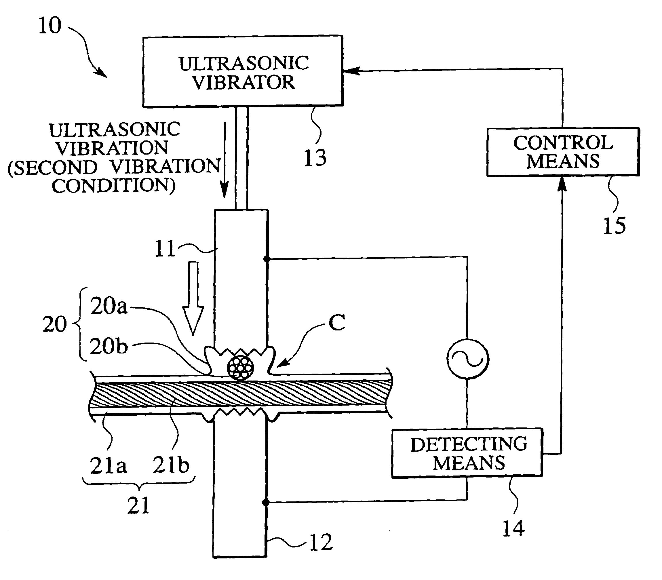
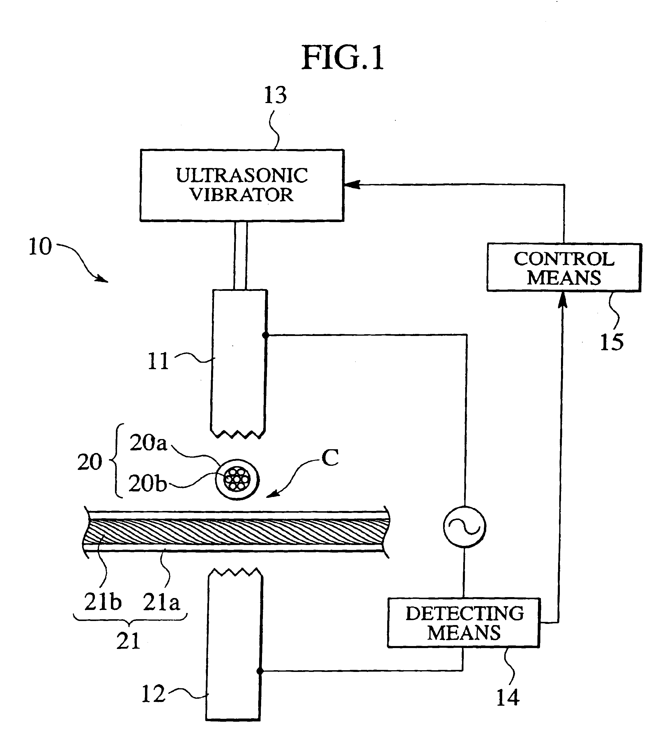
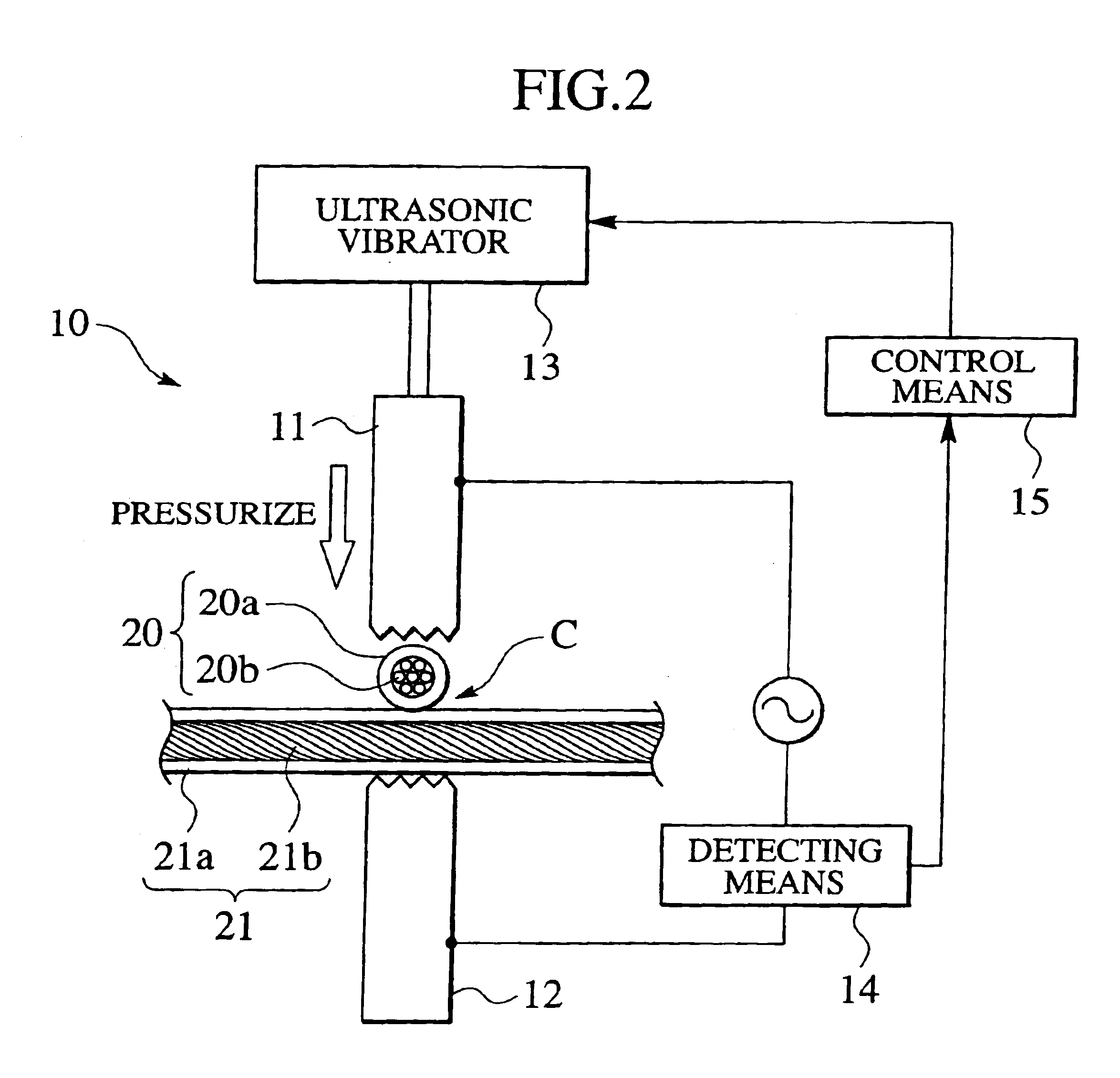
[0024]An ultrasonic bonding method of coated electric wires of the present embodiment is achieved by an ultrasonic bonding apparatus 10 shown in FIG. 1. The ultrasonic bonding apparatus 10 comprises a horn-side chip 11 and an anvil-side chip 12 which are vertically disposed such as to be opposed to each other. Coated electric wires 20 and 21 to be connected to each other are intersected with each other and disposed between the horn-side chip 11 and the anvil-side chip 12. The horn-side chip 11 is vertically movable, and the anvil-side chip 12 is fixed. If the horn-side chip 11 is lowered, the intersected portions C of the coated electric wires 20 and 21 disposed between the chips 11 and 12 are sandwiched under an appropriate pressurizing force in a pressurizing direction P.

[0025]An ultrasonic vibrator 13 is connected to the horn-side chip 11. Ultrasonic vibration gene...


PUM

PropertyMeasurementUnit
ultrasonic vibration forceaaaaaaaaaa
timeaaaaaaaaaa
resistanceaaaaaaaaaa

Abstract

Intersected portions (C) of coated electric wires 20 and (21) are sandwiched and pressurized between a horn-side chip (11) and an anvil-side chip (12) (sandwiching step). Ultrasonic vibration force determined by a first vibration condition is applied to the horn-side chip (11) to melt insulators (20a) and (21a) of the coated electric wires (20) and (21) (insulator-melting step). A time point when conductors (20b) and (21b) of the coated electric wires (20) and (21) come into contact with each other is automatically detected by the melting of the insulators (20a) and (21a) (conductor contact-detecting step). After the conductors came into contact with each other, ultrasonic vibration force determined by a second vibration condition is applied to the horn-side chip (11), thereby bonding the conductors (20b) and (21b) to each other (conductor-bonding step).

Description

TECHNICAL FIELD[0001]The present invention relates to an ultrasonic bonding method of coated electric wires in which coated electric wires to be bonded are intersected with each other without removing insulator, and intersected portions of the wires are bonded to each other by ultrasonic vibration. The invention also relates to an ultrasonic bonding apparatus using the method.BACKGROUND ART[0002]In an ultrasonic bonding of coated electric wires, the coated electric wires are subjected to ultrasonic vibration and pressurizing force at the same time, thereby bonding the wires to each other. The ultrasonic bonding is a technique for connecting electric wires to each other as disclosed in Japanese Patent Application Laid-open No. H9-29445.[0003]In this technique, upper and lower portions of intersected portions of the electric wires to be connected to each other are sandwiched between a horn-side chip and an anvil-side chip. In this state, ultrasonic vibration is applied to the horn-sid...

Claims


Application Information

Patent Timeline
Patent Type & Authority Patents(United States)
IPC IPC(8): B23K20/10B23K101/38H01R43/02
CPCB23K20/10B23K2101/38
Inventor KONDO, MASAYUKI
Owner YAZAKI CORP
Why Eureka
Try Eureka