Portable wireless remote monitoring and control systems

a wireless remote monitoring and control system technology, applied in the field of security and monitoring systems, can solve the problems of frozen or burst pipes in the plumbing, difficult to uninstall the system and move it to another location, and the most expensive and difficult to install residential and commercial monitoring systems available today, etc., to achieve convenient installation and setup, easy to program, and quick system setup

Active Publication Date: 2017-09-19
MOSES THOMAS LAWRENCE
View PDF29 Cites 105 Cited by
  • Summary
  • Abstract
  • Description
  • Claims
  • Application Information

AI Technical Summary

Benefits of technology

[0009]Therefore, it would be advantageous to provide a programmable wireless remote monitoring and control system that is easy to install and set up, requiring no wiring, and which is portable, so that a user can easily unplug and remove the components from one location and quickly set the system up in another location. Moreover, it would be desirable to provide a system that monitors against burglary and trespass, as well as monitoring people with high-risk medical conditions, and further, that monitors the electrical, plumbing and environmental systems to ensure proper operation. Finally, it would be desirable to provide such a system described above, which would also allow a user to remotely control (eith

Problems solved by technology

These systems may include temperature monitors to ensure that the temperature inside the home does not fall below freezing during the winter, which may result in frozen or burst pipes within the plumbing.
Additionally, one issue with current home monitoring and security systems is that interaction with the system requires either typing numbers into a keypad, tapping on a touch screen, or using a personalized fob.
Most of the residential and commercial monitoring systems available today are expensive and difficult to install, requiring in-wall wiring and trained technicians to p

Method used


Image

  • Portable wireless remote monitoring and control systems
  • Portable wireless remote monitoring and control systems
  • Portable wireless remote monitoring and control systems

Examples


Embodiment Construction

Overview

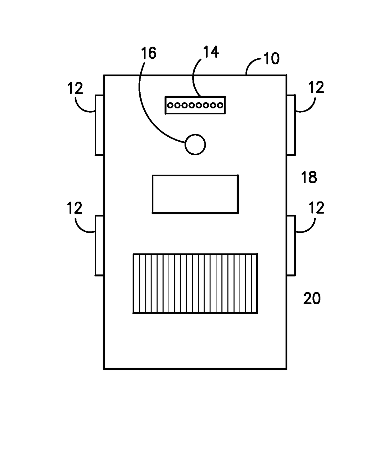
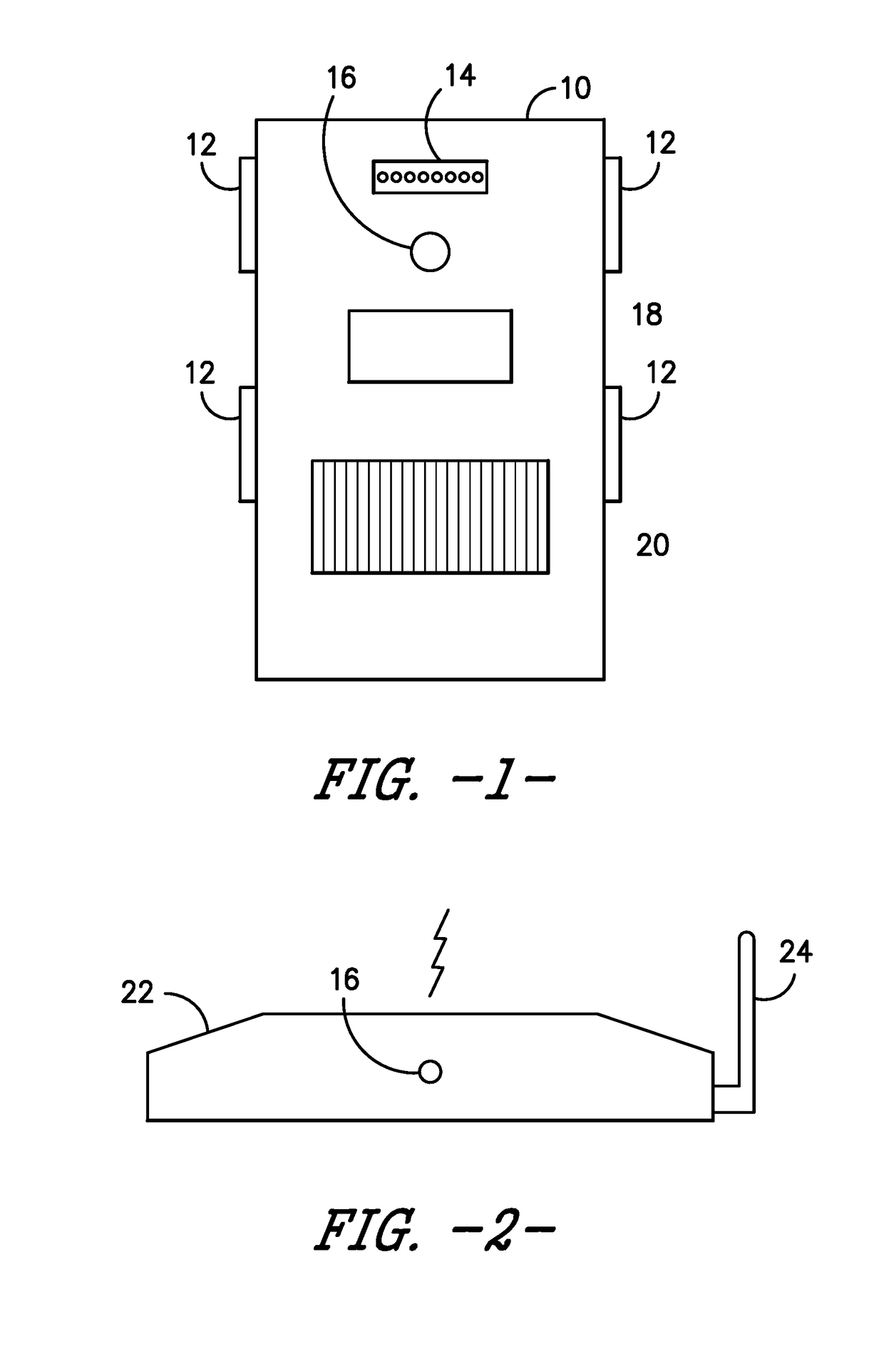
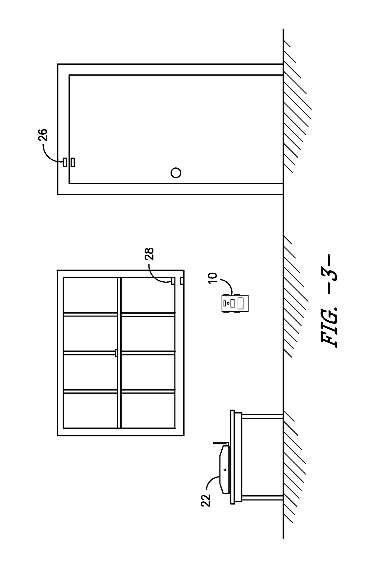
[0024]The present invention includes, in a first embodiment, a base unit 22 that plugs into a standard electrical outlet, along with a series of sensor units 10. The base unit 22 and the sensor units 10 include means for two-way communications, so that the sensor units 10 may transmit data collected by the sensors to the base unit 22, and the base unit 22 may transmit data or instructions to the sensor units 10. Preferably, the transmissions are wireless, and may be any type of wireless communications, including Bluetooth, radio frequency, sonar, laser, or any other suitable type of wireless communication.

[0025]As used herein, the terms “wi-fi,”“wifi” or “WIFI” mean generally a local area wireless computer networking technology that allows electronic devices to connect to the network, mainly using the 2.4 gigahertz (12 cm) UHF and 5 gigahertz (6 cm) SHF ISM radio bands.

[0026]The Wi-Fi Alliance defines Wi-Fi as any “wireless local area network” (WLAN) product based on the Ins...


PUM


Abstract

A user-programmable portable wireless remote monitoring system includes a base unit, a series of sensor units and a remote control device. The base unit is connected to the internet, and receives wireless alerts from sensor arrays deployed in the sensor units. When the sensor units detect a problem, then they send an alert to the base unit, which then relays the alert to the remote control device that is preferably a smart phone, tablet, or the like, including software for operating the system. The system may also incorporate smart outlets that are remotely operable by the remote control device, various monitors, a touchscreen, and wearable tracking devices to monitor a person within the home. The system is designed to provide security, home system monitoring, personal medical monitoring, and remote control of various electrical appliances. The system may also be controlled by using oral commands.

Description

BACKGROUND OF THE INVENTION[0001]Home security and monitoring systems have become enormously popular, and in many ways necessary, across the United States and the world in recent years. Different types of systems are used for different purposes. For instance, security systems are generally used to make sure that if the user's home, office, or other structure is broken into, the system may alert the user and / or a monitoring service, so that action can be taken to stop the crime in progress. Additionally, security systems may include lights and sirens to alert neighbors and to deter criminals from spending any more time in the vicinity of the screaming alarms and flashing lights.[0002]In recent years, another type of home monitoring system has become available, wherein the system is used to monitor people and their health. These types of systems generally include a wearable device that is worn by the person whose health is to be monitored, and the wearable device includes sensors that...

Claims


Application Information

Patent Timeline
IPC IPC(8): H04N7/14G08B21/04G08B13/196G08B25/10G08B25/00G08B25/01G08B25/08H04L12/28
CPCH04N7/147G08B25/10G08B25/016G08B13/19689G08B13/1966G08B13/19684G08B13/19697G08B21/0453G08B25/008G08B25/08H04L12/282G08B25/14H04L12/6418H04N7/185H04L12/4625G08B13/1672G08B19/005G05B15/02
Inventor MOSES, THOMAS LAWRENCE
Owner MOSES THOMAS LAWRENCE
Why Eureka
Try Eureka