
Link selection in lossy communication networks

a communication network and lossy technology, applied in the field of communication networks, can solve the problems of not providing sufficient variability for state of the art smart grid communication networks with time-varying links, and failing to deliver the routing performance needed in state of the art smart grid communication networks with time-varying links, and achieve the effect of quick and efficient link selection process

Active Publication Date: 2017-09-19
HITACHI ENERGY LTD
View PDF9 Cites 0 Cited by
  • Summary
  • Abstract
  • Description
  • Claims
  • Application Information

AI Technical Summary

Benefits of technology

[0008]It is therefore an objective of the invention to increase reliability of link selection for routing along lossy and time-variant links, in particular for a smart grid system. This objective is achieved by a method of selecting an inter-node link between a first node and a second node of a communication path and by a node for a packet oriented communication network according to the independent claims. Preferred embodiments are evident from the dependent patent claims, wherein the claim dependency shall not be construed as excluding further meaningful claim combinations.
[0026]In another embodiment, at least one of the two communication links is not a wireless link, and the two nodes are immobile, or stationary. This avoids the challenges related to the dynamic nature of the network topology and the resource constraints in networks with mobile wireless nodes.
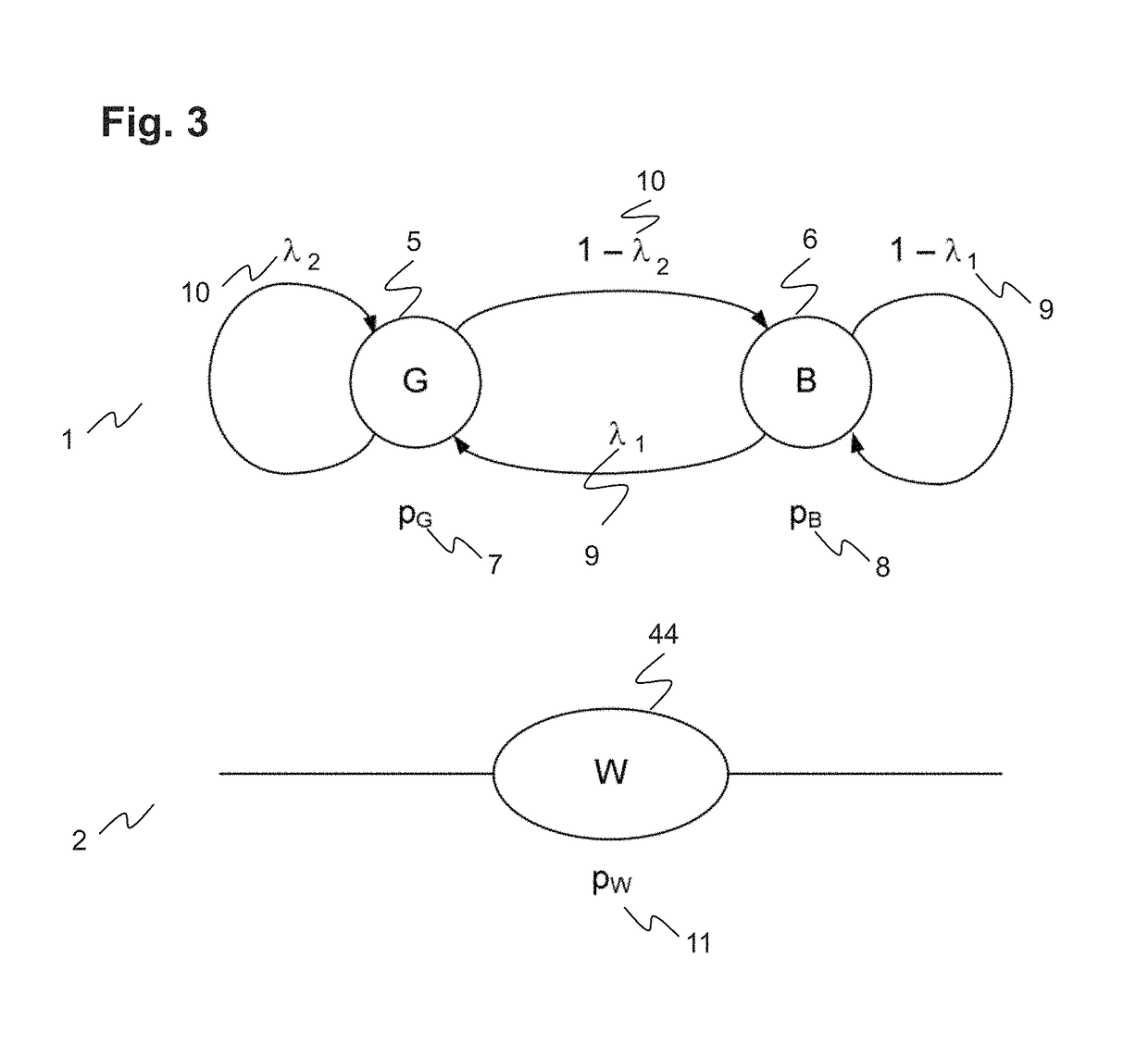
[0028]The advantage of the current invention is using a model based only on a few basic parameters of the underlying technology of a link as an input for future decisions on where to send the next packet, thus enabling a quick and efficient link selection process.

Problems solved by technology

This approach does not take into account any known variation of a link transmission rate or transmission success rate and, thus, fails to deliver routing performance needed in state of the art smart grid communication networks with time-varying links.
However, a reaction speed and a minimal probability for each link are the only parameters of this scheme and do not provide sufficient variability for state of the art smart grid systems.

Method used


Image

  • Link selection in lossy communication networks
  • Link selection in lossy communication networks
  • Link selection in lossy communication networks

Examples


Embodiment Construction

[0008]It is therefore an objective of the invention to increase reliability of link selection for routing along lossy and time-variant links, in particular for a smart grid system. This objective is achieved by a method of selecting an inter-node link between a first node and a second node of a communication path and by a node for a packet oriented communication network according to the independent claims. Preferred embodiments are evident from the dependent patent claims, wherein the claim dependency shall not be construed as excluding further meaningful claim combinations.

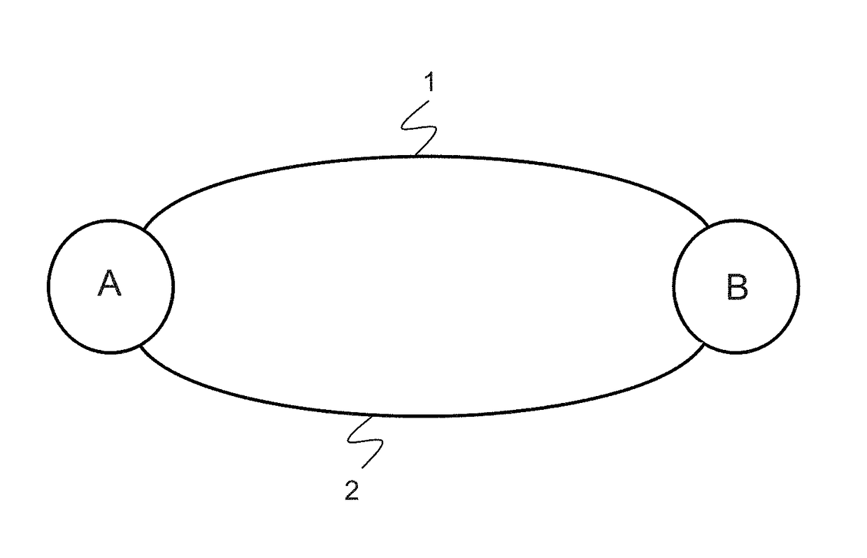
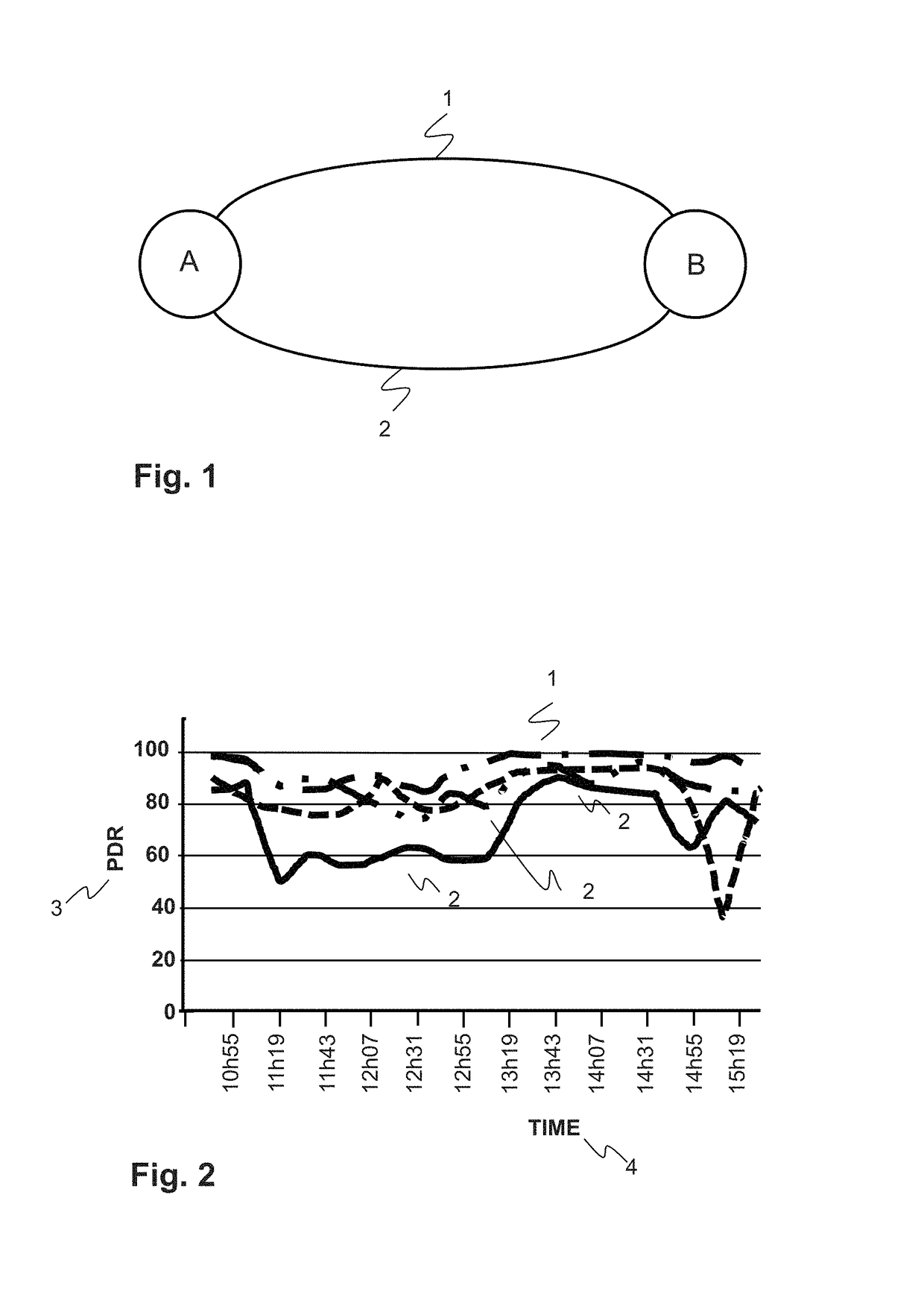
[0009]According to the invention, a communication link between a first node such as a router A and a specific neighbouring second node B of a communication path from a source to a destination in a packet oriented communication network is selected as follows. The two nodes are connected via a first communication link that has stochastic or time variable properties due to the lossy underlying communication technolo...


PUM


Abstract

The present disclosure encompasses establishing and maintaining a routing protocol based on a measured link metric p, such as for a smart grid communication system. A link between a first node such as a router A and a neighbouring second node B of a communication path from a source to a destination in a packet oriented communication network is selected wherein the two nodes are connected via first and second communication links. An updated link metric p(t+1) at a point in time t+1 of the first communication link is determined. The first or the second communication link is selected for transmitting a further packet from node A to node B by comparing the updated link metric p(t+1) to a threshold pthr.

Description

FIELD OF THE INVENTION[0001]The invention relates to the field of establishing and maintaining a communication route based on a measured link metric, in particular for a communication network for a smart grid. Specifically, the present invention relates to a method of and a system for selecting a link between two nodes.BACKGROUND OF THE INVENTION[0002]The process of selecting a path in a network along which to send network traffic is generally referred to as routing. The overall traffic performance of the network depends heavily on the selected path. In packet communication networks, routing directs packet from their source to their ultimate destination through intermediate nodes. These nodes are typically hardware devices such as routers, bridges, gateways, etc.[0003]The path to be selected comprises several links between nodes of the network. The link through which to send traffic is chosen according to a metric. Thus, for network performance the chosen metric is of great importan...

Claims


Application Information

Patent Timeline
Patent Type & Authority Patents(United States)
IPC IPC(8): H04L12/707H04W40/12H04W76/02H04L12/721H04L45/24H04L45/247
CPCH04W40/12H04L45/22H04W76/02H04L45/124Y02B60/50H04W76/10Y02D30/70
Inventor DZUNG, DACFEYPIGNOLET, YVONNE-ANNE
Owner HITACHI ENERGY LTD
Learn More