Fiber reinforced resin gear, method of forming fiber reinforced resin gear by injection molding, fiber reinforced resin rotary body, method of forming fiber reinforced resin rotary body by injection molding

a technology of fiber reinforced resin and rotary body, which is applied in the direction of mechanical equipment, other domestic objects, hoisting equipment, etc., can solve the problems of deteriorating roundness of fiber reinforced resin gear after forming, increasing the cost of machining the injection molding die, and decreasing the degree of freedom in design. , to achieve the effect of improving the roundness of the gear or the rotary body, increasing the cost of machining the injection molding die, and decreasing the degree of freedom

Active Publication Date: 2017-09-26
ENPLAS CORP
View PDF14 Cites 0 Cited by
  • Summary
  • Abstract
  • Description
  • Claims
  • Application Information

AI Technical Summary

Benefits of technology

[0011]Accordingly, it is an object of the invention to provide a fiber reinforced resin gear, a fiber reinforced resin rotary body and a method of forming the fiber reinforced resin gear and the fiber reinforced resin rotary body by injection molding which can improve roundness of the gear or the rotary body without increasing a cost of machining an injection molding die and without decreasing the degree of freedom in design.
[0016]According to the aspects of the invention, the orientation of reinforcing fibers is aligned in the same direction by the ejector pins at the time of performing injection molding and hence, roundness of a tooth portion (cylindrical portion) of the fiber reinforced resin gear (fiber reinforced resin rotary body) can be improved without using an expensive injection molding die whose number of pin point gates is increased.

Problems solved by technology

However, it has been known that such a fiber reinforced resin gear has a drawback in that the difference in shrinkage ratio attributed to non-uniformity of the fiber orientation of reinforcing fibers is generated so that roundness of the fiber reinforced resin gear after forming is deteriorated.
However, in the fiber reinforced resin gear 110 according to the second example of related art, it is necessary to apply machining to the injection molding die to increase the number of pin point gates 112, thus causing the drawback of increasing a cost of machining the injection molding die.
Accordingly, with respect to the fiber reinforced resin gear 120 according to the third example of related art, for example, there arises a case where radial ribs or circumferential ribs cannot be formed on side surfaces of the web 128, although it is desirable to form such ribs, thus causing the drawback of decreasing the degree of freedom in design.
Further, in the fiber reinforced resin gear 120 according to the third example of related art, when the formation of the plurality of holes 127 in the web 128 is not allowed from a viewpoint of strength of the fiber reinforced resin gear 120, there arises a drawback that the fiber reinforced resin gear 120 of the third example is not useful.

Method used


Image

  • Fiber reinforced resin gear, method of forming fiber reinforced resin gear by injection molding, fiber reinforced resin rotary body, method of forming fiber reinforced resin rotary body by injection molding
  • Fiber reinforced resin gear, method of forming fiber reinforced resin gear by injection molding, fiber reinforced resin rotary body, method of forming fiber reinforced resin rotary body by injection molding
  • Fiber reinforced resin gear, method of forming fiber reinforced resin gear by injection molding, fiber reinforced resin rotary body, method of forming fiber reinforced resin rotary body by injection molding

Examples


Embodiment Construction

[0027]Hereinafter, an embodiment of the invention is explained by reference to drawings.

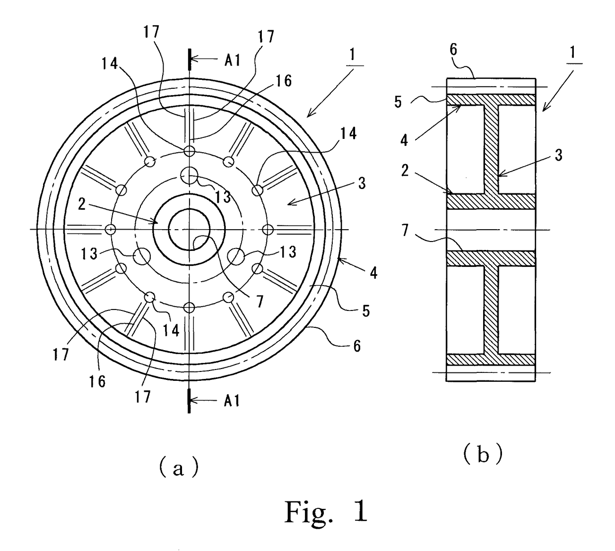
[0028]FIG. 1A and FIG. 1B are views showing a fiber reinforced resin gear 1 which constitutes a fiber reinforced resin rotary body according to the embodiment of the invention. FIG. 1A is a front view of the fiber reinforced resin gear 1, and FIG. 1B is a cross-sectional view of the fiber reinforced resin gear 1 taken along a line A1-A1 in FIG. 1A.

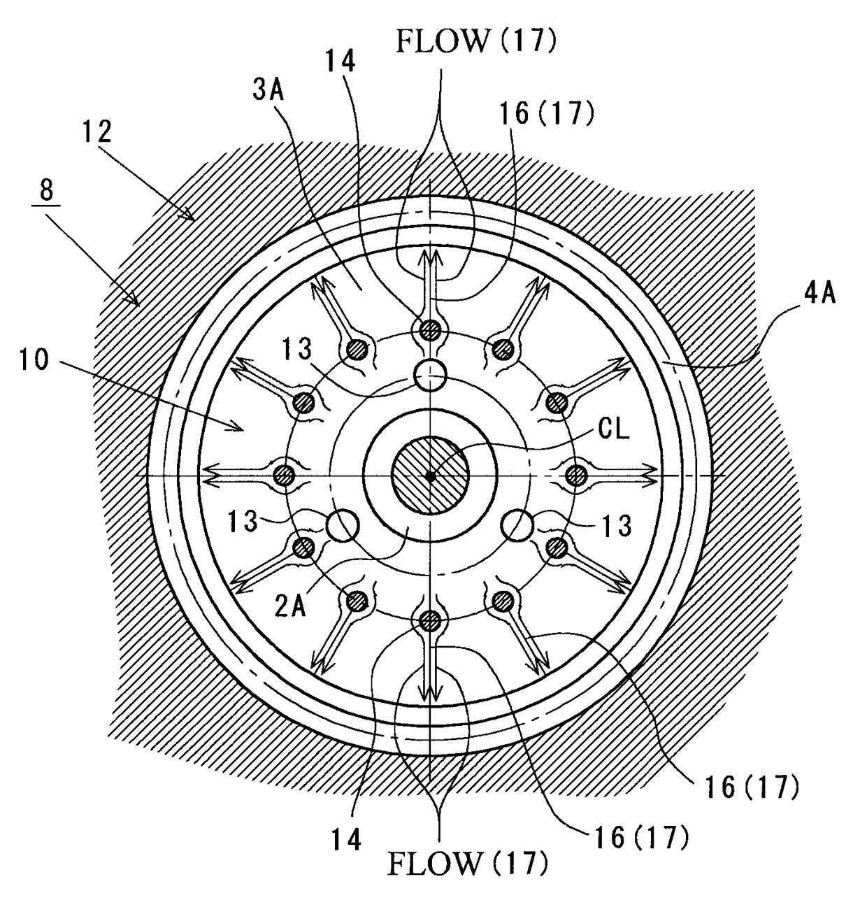
[0029]As shown in FIG. 1A and FIG. 1B, the fiber reinforced resin gear 1 of this embodiment includes: a circular-cylindrical boss portion 2 which is positioned at a center portion of the gear 1; a disk-shaped web (disk-shaped portion) 3 which extends outward in the radial direction from a center portion of the boss portion 2 in the axial direction; and a circular cylindrical tooth portion (cylindrical portion) 4 which is connected to a radially outer end of the web 3. The tooth portion 4 is formed such that a plurality of teeth 6 is formed on an outer p...


PUM

PropertyMeasurementUnit
helical angleaaaaaaaaaa
strengthaaaaaaaaaa
shrinkage ratioaaaaaaaaaa

Abstract

Plural ejector pins are made to project before a molten resin containing reinforcing fibers is injected into an inside of a cavity through pin point gates in a web forming portion in the inside of the cavity and at positions outside the pin point gates in a radial direction. The ejector pins are retracted from the inside of the cavity after a flow of the molten resin containing reinforcing fibers injected into the inside of the cavity through the pin point gates impinges on the ejector pins and is divided and before a tooth portion forming portion in the inside of the cavity is filled with the molten resin containing reinforcing fibers. Accordingly, weld lines which extend along the radial direction are formed at positions outside the ejector pins in the radial direction, and the molten resin is filled in portions formed after the ejector pins are retracted.

Description

BACKGROUND OF THE INVENTION[0001]1. Field of the Invention[0002]The present invention relates to a fiber reinforced resin gear formed using a resin which contains reinforcing fibers, a fiber reinforced resin rotary body, and a method of forming the fiber reinforced resin gear and the fiber reinforced resin rotary body by injection molding.[0003]2. Description of the Related Art[0004]Conventionally, in a power transmission mechanism of various machines such as an automobile, an industrial machine or a copier, a fiber reinforced resin gear having high strength is used in place of a metal-made gear. Such a fiber reinforced resin gear is manufactured by injecting a molten resin which contains reinforcing fibers such as glass fibers or carbon fibers into the inside of a cavity. However, it has been known that such a fiber reinforced resin gear has a drawback in that the difference in shrinkage ratio attributed to non-uniformity of the fiber orientation of reinforcing fibers is generated ...

Claims


Application Information

Patent Timeline
Patent Type & Authority Patents(United States)
IPC IPC(8): F16H55/06B29C45/00B29C45/40B29C45/27B29K105/14B29L15/00
CPCF16H55/06B29C45/0005B29C45/0025B29C45/401B29C45/2708B29C45/40B29C2045/0006B29C2045/0043B29C2045/0049B29K2105/14B29L2015/003F16H2055/065Y10T74/1987
Inventor HASHIMOTO, MASAOMIYANAGISAWA, KAZUMA
Owner ENPLAS CORP
Why Eureka
Try Eureka