Digital loupe device

a technology of loupes and loupes, which is applied in the field of digital loupes, can solve the problems of musculoskeletal problems, pain, and weakness of above two optical instruments, and achieve the effects of reducing the risk of eye strain, and improving the quality of surgery

Inactive Publication Date: 2017-09-26
TAM WENG KONG +1
View PDF12 Cites 11 Cited by
  • Summary
  • Abstract
  • Description
  • Claims
  • Application Information

AI Technical Summary

Benefits of technology

[0012]The present invention is to provide a digital microsurgical visualization device and its view stabilizing method. A capturing element with auto-focusing function is used to capture the image of the surgical view and, according to the operator's command which is either verbally or digitally; the surgical view will be, but not limited to, zoom in / out, recorded or stabilized accordingly. The lighting element adjusts light intensity and focus accordingly in order to achieve a proper brightness of image at varying distance. The desired view image will be shown on the Virtual Retinal Display (VRD) display module for viewing during the surgery. VRD provides image display technology in which the laser beam of the image will directly scan onto the retina inside the eyes. This method enables the surgeons to move freely, instead of prolonged fixing at a close distance, and reduces the risk of eye strains. The surgery quality is improved and the surgical time is shortened. Both patients and surgeons are finally benefited.
[0014]The present invention also provides an automatic view stabilizing method that uses at least one lighting capture module that is set on at least one axial rotation module. First, the lighting capture module illuminates the target view, capture the image of the surgical view and send an according feedback signal. Then, the feedback signal received is used to move the lighting capture module via the axial rotation module in order to keep a shifted surgical view back to the original location previously. If the feedback signal also reveals an inappropriate light intensity of the image either brighter or darker than the threshold set forth in system, the lighting element inside a lighting capture module will be adjusted accordingly in order to provide proper light intensity and focus on the surgical view in order to keep the image in good brightness condition for the surgeon. Finally, the two images captured by the lighting capture modules on both sides have to be automatically aligned and superimposed at some points so that the operator will not suffer from double visions of the images presented.

Problems solved by technology

Medical surgeons are often required to manipulate very small hard and soft tissue which is usually difficult to be observed by un-aided eyes.
However, the above two optical instruments have weaknesses.
Firstly, they require the operating surgeons keeping at some fixed working distance and posture throughout the whole operation.
Hence, it leads to musculoskeletal problems and pain, especially, over the back spines of surgeons.
Secondly, prolonged focusing through optical lens in the loupe or microscope during surgery will cause eye strains.
Thirdly, in high magnification mode, the magnified view shifts unsteadily with unintentional movement of the observer's head.
Such motion increases focusing difficulty and further affect / damage / endanger visibility.
These complications of using the surgical loupes and microscopes are not only harmful to the health of the surgeons, but directly affect the performance of the operation and quality of the treatment.

Method used


Image

  • Digital loupe device
  • Digital loupe device
  • Digital loupe device

Examples


Embodiment Construction

[0022]The detailed description and technical contents of the present invention will become apparent with the following detailed description accompanied with related drawings. It is noteworthy to point out that the drawings is provided for the illustration purpose only, but not intended for limiting the scope of the present invention.

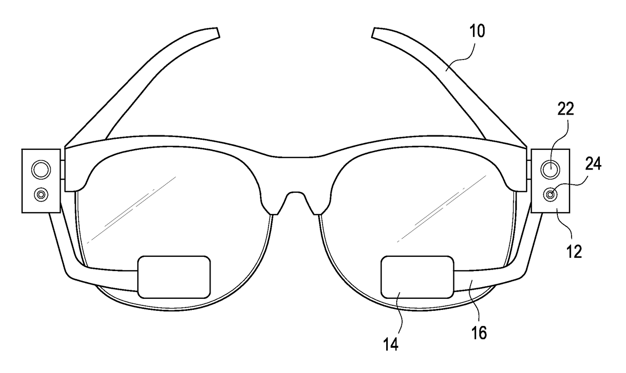
[0023]FIGS. 3 to 5 show a preferred embodiment of the digital loupe device of the present invention. The digital loupe device is preferably a wearable or head-mounted device that is worn on the surgeon's head. The surgeon can observe a magnified surgical view on the display modules of the digital loupe device.

[0024]The digital loupe device comprises a wearable frame 10, a pair of lighting capture modules 12, at least one axial rotation modules 18,20, a pair of display modules 14 and at least one control unit 26. The wearable frame 10 is preferably an eyeglass or head-mounted frame. The wearable frame 10 can be worn on the surgeon's head. Here the wearabl...


PUM


Abstract

The present invention provides a digital loupe device and its automatic view stabilizing method. The digital loupe device is worn or head-mounted on the operator's head via a wearable frame that is connected to a plural of axial rotation modules. A pair of lighting capture modules set on the axial rotation module is used to illuminate the target view and capture the image of the target view in order to send feedback signal. Both the lighting capture modules and axial rotation modules are electronically connected to at least one control unit. The control unit, base on the feedback signal received, moves the lighting capture modules via the axial rotation modules till the desired image of the target view is obtained. The display module connected to the wearable frame can show the captured image and information provided by the control unit.

Description

BACKGROUND OF THE INVENTION[0001]Field of the Invention[0002]The present invention relates to a digital microsurgical visualization device. More specifically, the invention comprises a digital loupe device which optionally replaces the conventional surgical loupe and microscope.[0003]Description of Prior Art[0004]Microsurgery has been increasingly being practiced in hospitals. Medical surgeons are often required to manipulate very small hard and soft tissue which is usually difficult to be observed by un-aided eyes. Some of those tiny surgical objects, such as vascular structure, nerve and other tissue, may have the diameter of less than 1 mm. Precise magnifying equipment, thus, is crucial for a microsurgery.[0005]Please refer to FIG. 1 and FIG. 2, two most commonly used surgical visual tools, namely binoculars surgical loupes and binocular surgical microscope are showed. The features of surgical loupe and microscope are compared and shown in the below table.[0006]LoupesMicroscopesm...

Claims


Application Information

Patent Timeline
Patent Type & Authority Patents(United States)
IPC IPC(8): G02B27/01G02B25/00
CPCG02B27/0172G02B25/004G02B2027/0138G02B2027/0154G02B2027/0178
Inventor TAM, WENG-KONGTSE, KAI-POK
Owner TAM WENG KONG
Why Eureka
Try Eureka