Antenna matching apparatus

a technology of antenna matching and antenna, applied in the field of antenna matching apparatus, can solve the problems of degrading the communication performance achieved by the carrier aggregation, and achieve the effects of suppressing the reduction of transmission-reception characteristics, excellent matching, and communication performan

Active Publication Date: 2017-09-26
MURATA MFG CO LTD
View PDF17 Cites 2 Cited by
  • Summary
  • Abstract
  • Description
  • Claims
  • Application Information

AI Technical Summary

Benefits of technology

[0010]Preferred embodiments of the present invention provide an antenna matching apparatus capable of suppressing reduction in transmission-reception characteristics in respective bands in carrier aggregation.
[0012]The antenna matching apparatus having the above configuration may be mounted in, for example, a mobile communication terminal and may be used in the following manner. The first terminal is connected to a transmission-reception circuit in the mobile communication terminal. A high band antenna is connected to either one of the second and third terminals. A matching element for the high band antenna is connected to the second and third terminals. A low band antenna is connected to either one of the fourth and fifth terminals. A matching element for the low band antenna is connected to the fourth and fifth terminals. Accordingly, the transmission-reception circuit in the mobile communication terminal is connected to the high band antenna with the matching element and the high pass filter (or the high pass filter and the first switch) interposed therebetween. The transmission-reception circuit in the mobile communication terminal is connected to the low band antenna with the matching element and the low pass filter (or the low pass filter and the second switch) interposed therebetween. The provision of the matching elements achieves excellent matching in both the high band and the low band. Accordingly, even when the low band and the high band are simultaneously used in carrier aggregation, the communication performance achieved by the carrier aggregation is realized.
[0013]According to various preferred embodiments of the present invention, it is possible to suppress reduction in transmission-reception characteristics in each band in the carrier aggregation to improve the communication performance.

Problems solved by technology

As a result, since the transmission-reception characteristics and so on in the other bands are reduced, the communication performance achieved by the carrier aggregation is degraded.

Method used


Image

  • Antenna matching apparatus
  • Antenna matching apparatus
  • Antenna matching apparatus

Examples


Embodiment Construction

[0040]Preferred embodiments of the present invention will herein be described in detail with reference to the attached drawings. The same reference numerals are used in the drawings to identify the same or corresponding components. A description of such components is not repeated.

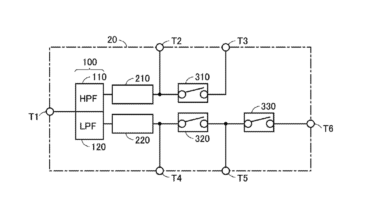
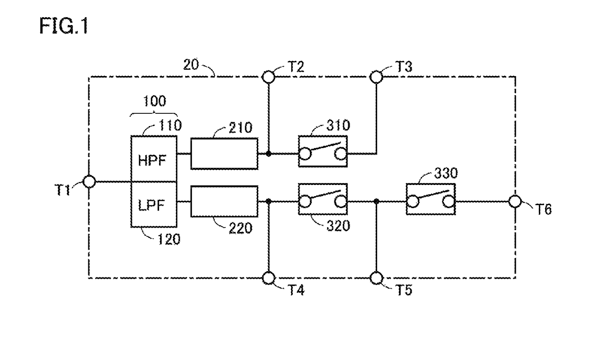
[0041]FIG. 1 is a diagram illustrating an antenna matching apparatus according to a preferred embodiment of the present invention. Referring to FIG. 1, an antenna matching apparatus 20 includes terminals T1 to T6, a diplexer 100, phase circuits 210 and 220, and switches 310, 320, and 330.

[0042]The diplexer 100 includes a high pass filter (HPF) 110 and a low pass filter (LPF) 120. The HPF 110 is used to transmit a signal in a high band (first frequency band). The LPF 120 is used to transmit a signal in a low band (second frequency band). The low band frequency is lower than the high band frequency. The frequency band of the high band is, for example, about 1,500 MHz to about 3,500 MHz and the frequency band ...


PUM


Abstract

A high pass filter includes a first end connected to a first terminal and is a filter that transmits a signal in a first frequency band. A second terminal is connected to a second end of the high pass filter. A first switch includes a first end connected to the second end of the high pass filter. A third terminal is connected to a second end of the first switch. A low pass filter includes a first end connected to the first terminal and is a filter that transmits a signal in a second frequency band lower than the first frequency band. A fourth terminal is connected to a second end of the low pass filter. A second switch includes a first end connected to the second end of the low pass filter. A fifth terminal is connected to the second end of the second switch.

Description

CROSS REFERENCE TO RELATED APPLICATIONS[0001]This application claims the benefit of priority to Japanese Patent Application 2014-075480 filed Apr. 1, 2014 and is a Continuation application of PCT / JP2014 / 080711 filed on Nov. 20, 2014. The entire contents of each application are hereby incorporated herein by reference.BACKGROUND OF THE INVENTION[0002]1. Field of the Invention[0003]The present invention relates to an antenna matching apparatus.[0004]2. Description of the Related Art[0005]Mobile communication terminals supporting multiple frequency bands (multiband mobile communication terminals) have hitherto been in practical use. The multiple frequency bands are composed of, for example, a combination of a relatively low frequency band (low band) and a relatively high frequency band (high band). Excellent transmission-reception characteristics are required of the mobile communication terminals in both the low band and the high band.[0006]Japanese Unexamined Patent Application Publica...

Claims


Application Information

Patent Timeline
Patent Type & Authority Patents(United States)
IPC IPC(8): H01Q7/00H03H7/18H03H7/01H01Q1/24H04B1/00H01Q21/29H03H7/40H03H7/38H01Q21/00H03H1/00H03H7/46
CPCH03H7/38H01Q1/243H01Q21/29H03H7/0115H03H7/18H03H7/40H03H7/46H04B1/0064H03H7/463H03H2001/0085H01Q21/30H01Q5/335
Inventor IWANAGA, MINORU
Owner MURATA MFG CO LTD
Why Eureka
Try Eureka