Vapor cooled shielding liner for cryogenic storage in composite pressure vessels

a composite pressure vessel and shielding liner technology, applied in the field of cryogenic storage tanks, can solve the problems of cracking of the tank insulation, unfavorable high-altitude use, and water-based materials that are not likely to be practical for high-altitude use, and achieve the effect of low volum

Active Publication Date: 2017-10-03
WASHINGTON STATE UNIVERSITY
View PDF3 Cites 9 Cited by
  • Summary
  • Abstract
  • Description
  • Claims
  • Application Information

AI Technical Summary

Benefits of technology

[0008]It is to be appreciated that the present example embodiments herein are directed to a cryogenic composite vapor cooled storage tank that is extremely lightweight and low volume with respect to the weight and volume of fluid that may be contained.

Problems solved by technology

However, a primary challenge with utilizing hydrogen fuel is storage.
However, typical tanks for storing compressed gaseous hydrogen have a weight of about 10 to 20 times that of the hydrogen stored, and are not likely practical for high-altitude, long-duration aircraft.
Moreover, liquid hydrogen powered long-endurance vehicles typically require tanks with sufficient insulation to prevent complete boil-off due to ambient heat for less than one to two weeks.
Nonetheless, such systems have inherent problems that include cracking of the tank insulation due to mismatched coefficients of thermal expansion and pressure fluctuation induced swelling and a need for configured vacuum jackets to be continually purged of residual gas via vacuum pumping due to excessive hydrogen permeation through the tank wall.
In addition, a weight intensive heat exchanger and electric heater are often required to heat the fuel to prevent condensation of air or water outside to piping outside the tank.
The most straightforward approach entails directly compressing the hydrogen and storing the room temperature gas in conventional high pressure vessels but the fuel density is not competitive from a capacity and performance standpoint with cryogenic hydrogen.
Liquid hydrogen is typically stored in spherical tank structures, however, there are difficulties in manufacturing and incorporating tank structures (e.g., spherical tank structures) into existing Unmanned Aerial Systems (UAS) systems.

Method used


Image

  • Vapor cooled shielding liner for cryogenic storage in composite pressure vessels
  • Vapor cooled shielding liner for cryogenic storage in composite pressure vessels
  • Vapor cooled shielding liner for cryogenic storage in composite pressure vessels

Examples


Embodiment Construction

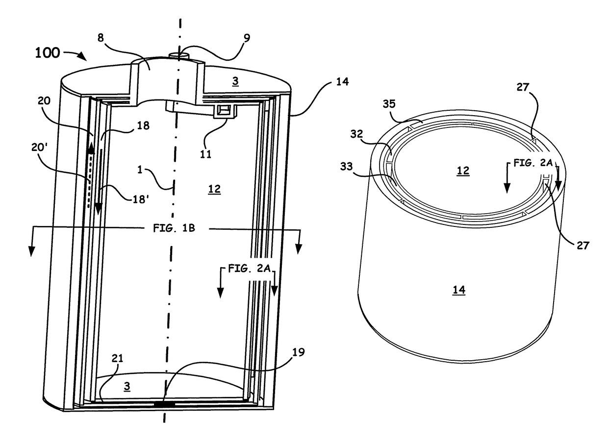
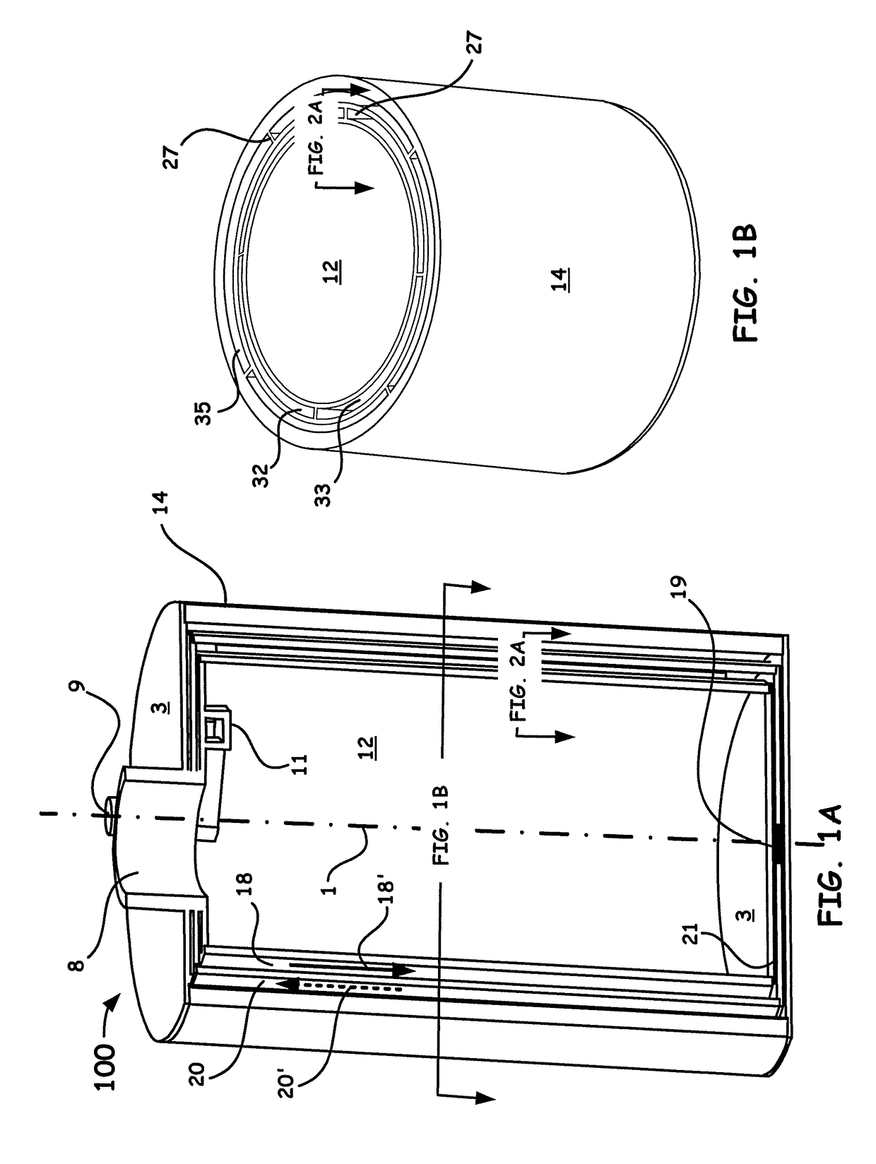
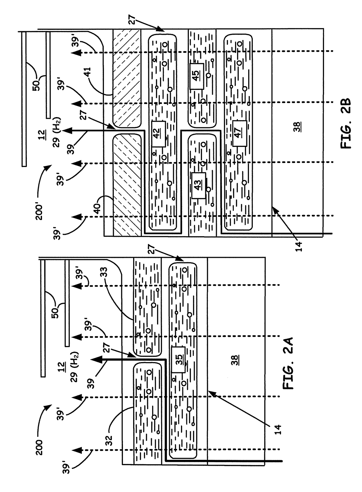
[0017]In the description of the invention herein, it is understood that a word appearing in the singular encompasses its plural counterpart, and a word appearing in the plural encompasses its singular counterpart, unless implicitly or explicitly understood or stated otherwise. Furthermore, it is understood that for any given component or embodiment described herein, any of the possible candidates or alternatives listed for that component may generally be used individually or in combination with one another, unless implicitly or explicitly understood or stated otherwise. It is to be noted that as used herein, the term “adjacent” does not require immediate adjacency. Moreover, it is to be appreciated that the figures, as shown herein, are not necessarily drawn to scale, wherein some of the elements may be drawn merely for clarity of the invention. Also, reference numerals may be repeated among the various figures to show corresponding or analogous elements. Additionally, it will be un...


PUM

PropertyMeasurementUnit
thicknessaaaaaaaaaa
thicknessesaaaaaaaaaa
temperatureaaaaaaaaaa

Abstract

A novel tank cryogenic-compatible composite pressure vessel that beneficially utilizes Vapor Cooled Shielding (VCS) is introduced to minimize thermal gradients along support structures and reduces heat loads on cryogenic systems. In particular, the configurations and mechanisms to be utilized herein include: providing for a desired number of passageways and a given thickness of the VCS, reducing the thermal conductivity of the VCS material, and increasing the cooling capacitance of the hydrogen vapors.

Description

BACKGROUND OF THE INVENTION[0001]The present application claims under 35 U.S.C. §119, the priority benefit of U.S. Provisional Application No. 62 / 033,028, filed Aug. 4, 2014, entitled: “Vapor Cooled Shielding Liner for Cryogenic Storage in Composite Pressure Vessels.” The disclosure of the foregoing application is incorporated herein by reference in its entirety.FIELD OF THE INVENTION[0002]The present embodiments herein relate to the field of storage tanks for fluid cryogens. In particular, the present embodiments herein relate to the field of cryogens such as, cryogenic fluid hydrogen stored in composite pressure vessels.DISCUSSION OF THE RELATED ART[0003]Cryogenic fluids, such as, hydrogen is known to be a desirable vehicular fuel for aerospace, marine, and terrestrial applications. Motivation comes from the fact that in many aerospace and unmanned aerial vehicle applications, the benefits of hydrogen outweigh the challenges. For example, beneficial aspects of hydrogen include the...

Claims


Application Information

Patent Timeline
Patent Type & Authority Patents(United States)
IPC IPC(8): F17C1/00F17C3/04
CPCF17C3/04F17C2201/0119F17C2201/054F17C2201/056F17C2203/0366F17C2203/0375F17C2203/0387F17C2203/0604F17C2203/0631F17C2203/0663F17C2221/012F17C2223/0161F17C2223/033F17C2260/033F17C2270/0105F17C2270/0168F17C2270/0186Y02E60/321F17C3/10F17C2203/0619F17C2203/0636F17C2203/066F17C2203/0682F17C2209/21F17C2223/043F17C2270/0194Y02E60/32
Inventor LEACHMAN, JACOB WILLIAMADAM, PATRICK MARSHALL
Owner WASHINGTON STATE UNIVERSITY
Why Eureka
Try Eureka